
I mentioned in my last post that M.G. Scroggie, writing under the pseudonym “Cathode Ray” wrote reminiscences of years of interviewing in an article in “Wireless World”. Many “Cathode Ray” articles can be found at the site http://www.keith-snook.info/wireless-world-magazine/wireless-world-articles.html, but not, as far as I can tell, this particular one.
Like me, Scroggie found that the simplest questions can be useful for distinguishing between candidates on the most subtle points. He had a favourite question. He would present the candidate with this circuit:
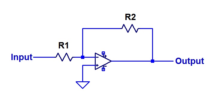
His question was “What is the Voltage Gain of this circuit?”
Nearly all candidates would have a crack at it and write:
R2
Voltage Gain = ———–
R1
Scroggie would reply: “No. That is not what I want.”
The candidate would then try complicating the matter in all sorts of ways. They would offer a more complicated expression that took into account the finite gain of the op-amp. They would introduce the op-amp dominant pole frequency and derive an equation that was an expression of frequency.
To all these efforts, Scroggie would say “No”.
In the end he had to tell them what he was after: a minus sign!
If the circuit is inverting, then the voltage gain is a negative number. Scroggie was a stickler for details such as this, and I learned several rules from him for conventions that can help me from making errors by such means as getting the sign of an expression wrong.
That Scroggie article appeared many years ago, but I have never forgotten the lesson. Thus when James posed his question, which I repeat here:
“Design a one transistor amplifier with a gain of three.
– 9V supply rail.
– 5k drive impedance to drive YOUR amplifier.
– 22k load impedance driven from YOUR amplifier.
– 20-20kHz operation.
– gain of 3.
– AC coupling required.
– Output voltage of 1Vp-p.
– 1 transistor only.”
“This is reasonably easy,” he wrote, “but requires getting a lot of things in line.”
I was alerted to possible complications when I read the “requires a lot of things in line” bit.
I interpreted this as a potentially tricky question because the required gain is a positive number. This indicates that the amplifier is to be non-inverting. The alternative interpretation, that James (like Scroggie’s candidates) had simply ignored the sign, seemed less likely in the face of those warning words. So I had a crack at it. Here is my effort.
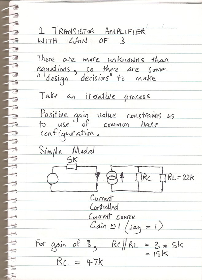

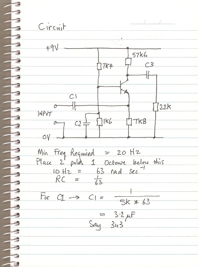
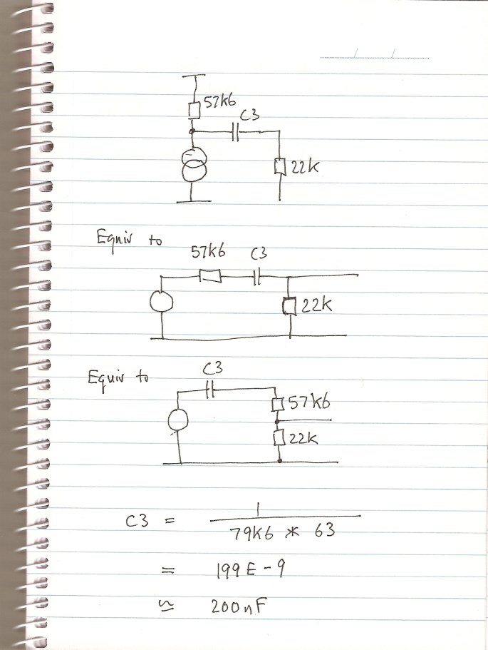
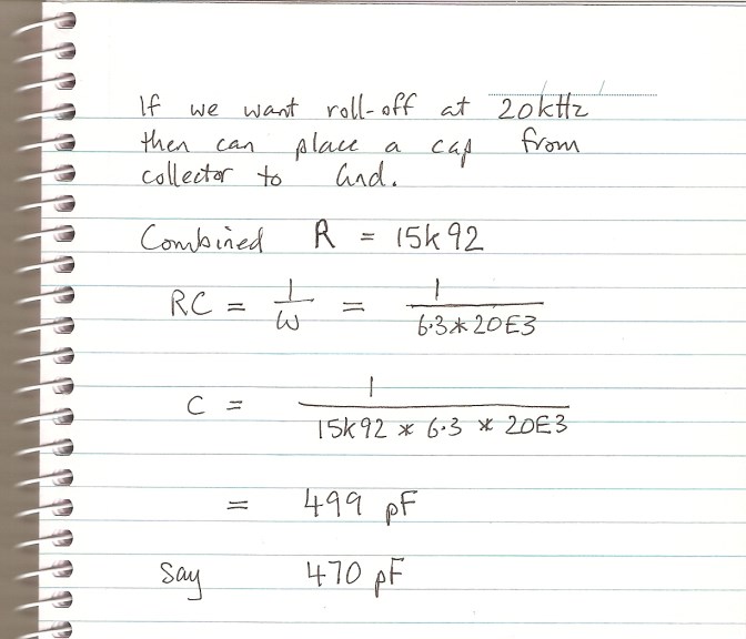
Now, first of all, I will mark my own work. What you see above is what I was able to do in examination conditions, although I have written it out again more neatly for you.
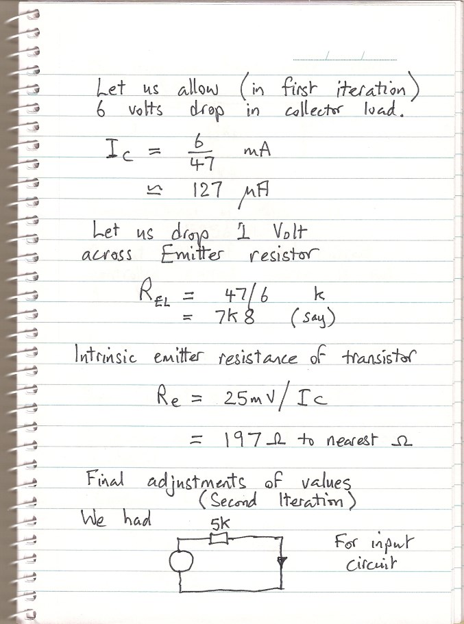
In the hand written text above, I have used the term “Transresistance” which is WRONG! What I meant was “Reciprocal of Transconductance” which is not the same thing!
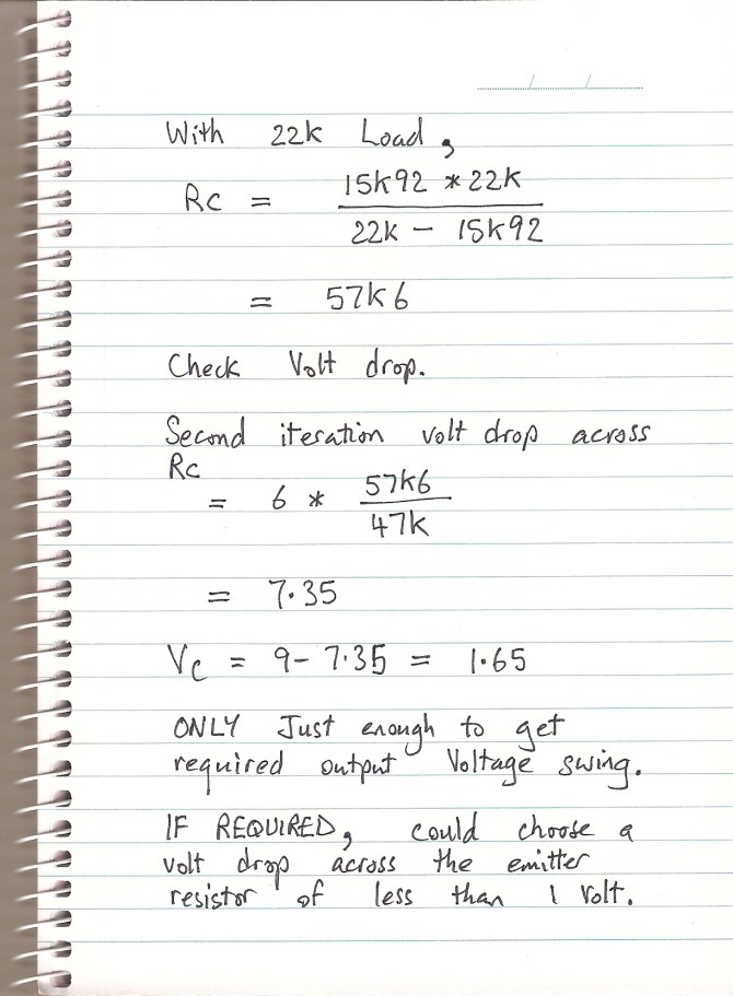
I realized later that I could reduce the collector current, and consequently the volt drop in the collector load resistor just by increasing the value of the emitter load resistor. Indeed, after I had put it up on the simulator, I did increase the emitter load to 9k1, and the small signal response did not change at all. There would have been a little more headroom without transistor saturation, and although I have not even estimated the effect of temperature, the more room to move the circuit has, the more it will be tolerant of changed bias conditions as the VBE changes.
So I sort of had a circuit together in my quick single session with a note pad and a calculator. I was certainly able to make some minor improvements over the next couple of hours, but those hours would not have been available in a job interview test!
How did I do?
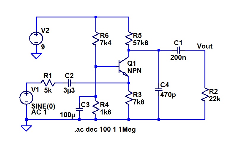
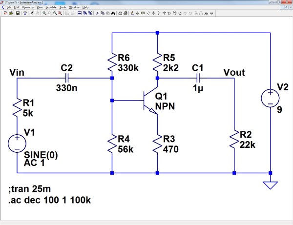
Here is the circuit in LTspice before I changed the emitter load resistor.
.
.
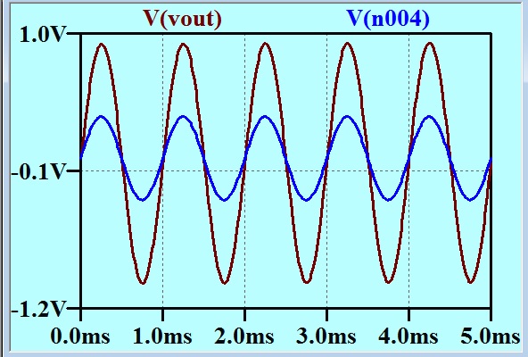
It has a gain of 3 with no inversion.
.
.
This is not a Bode plot. The vertical axis is linear. ALMOST made a gain of 3! Could quickly tweak this in a real world situation, of course.
.
.
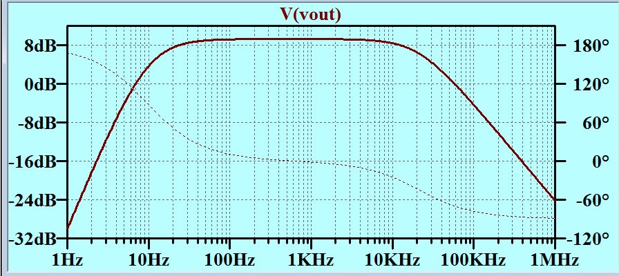
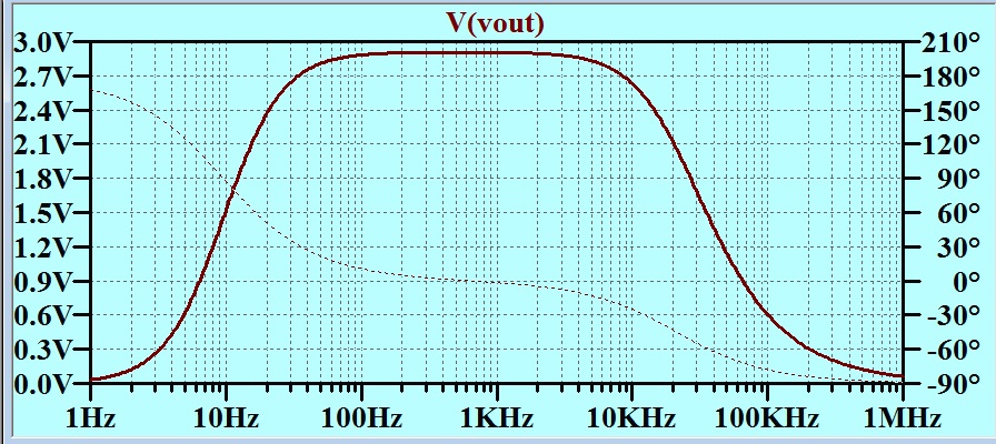
Here is a Bode plot showing how well I did at setting the bandwidth limits.
All this is all very well, but it turns out that I took myself (and you) up a wattle, as this was NOT what the examiner wanted. James was not being pedantic about the minus sign! He wrote to me later to show what he wanted. Here it is:
Oh Well! I guess I failed that test!
Hello R,
I notice that in your pedantry you forgot the bit:
“I sat a test 20 years ago that asked:
Design an amplifier……”
I didn’t realise personnel correspondence would be quoted without review, I’ll be a little more careful next time!
J.
No, Richard! You passed. The test was a failure.
I remember in 4th year of my degree we had an exam with a mistake in the question that made it impossible – it took about an hour of discussion through a third party to the lecturer before he accepted that there was an error. We got an extra hour to do the paper! 4 hours…. Uggggghhh!
Richard, I would have assumed that the question implied a small-signal voltage gain of magnitude 3 (approx.). Since the question did not specify a signal frequency or amplitude range, it is reasonable to assume that a simple interpretation was expected.
Oops… Ignore my previous post. I didn’t read the original question carefully. I still think it’s reasonable to ignore the sign of the gain in a small signal ac coupled amplifier. MJB