Roof
Initial aesthetics requirements
The existing building had a lean-to roof up against the concrete block wall. For the rebuild, I decided to have a gable roof for aesthetic reasons. For a given roof slope, this gives a lower maximum height for a given ceiling clearance than the lean-to. It was necessary to minimize the maximum roof height to reduce the visual imposition on the back yard.
As the building is not
a recatangle shape in plan (the rear wall is shorter than the front
wall), I had to face a choice between:
(a) Running the ridge
beam at an angle so that it meets both front and rear walls in the
middle,
(b) Running the ridge
beam parallel to the concrete block wall (and right angles to the
front and rear), and placed centrally on the rear wall.
and
(c) Running the ridge
beam parallel to the concrete block wall (and right angles to the
front and rear), and placed centrally on the front wall.
(a) was rejected on the
grounds of needless complication.
(b) was rejected on
aesthetic grounds. On the drawing, it appeared that it was necessary
for the roof to be symmetrical at the front, or it looked shithouse.

Front
wall could look ok if the ridge was central.
This meant that in plan, all corners were to be right angles except for the boundary side wall (called the Bazza wall) which took up all the variation in building width from front to back.
Details
Various decisions had to be made about what height some features would be set at. It was decided that refters would be placed so that their top face would match the height of the top of the ridge beam so that the plywood ceiling lining could be nailed to the rafters and to the top of the ridge beam. The rafters were (nom.) 100 x 50 OBHW wooden rails from the Wombat Creek Tramway. A compomise was chosen for thermal insulation thickness of 75 mm. This gave R1.5. That is 1.5 m^2 for every Watt heat transfer for every Kelvin delta T. (The stud walls have 90 mm thickness – R2.5)
R value (m2K/W)

The following drawing was drafted early in the project as it determined detail of the front and rear stud walls.
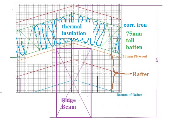
Some minor changes were made later, but this drawing set the basic roof plan.
The roof gutter design is for deep steeply bottomed channels that are within the building plan area. The Bazza wall one is set inside the wall between the external and internal cladding, above the studs. The roof gutter along the concrete block wall is set is a space created by the design of the steel structure. More details in the pages for the walls.
Plywood that had been obtained gratis from Barry Paul was selected for the ceiling. The most efficient use of available sheet sizes dictated that there be some exposed butt joints, but this seemed to be ok. The trick was to place the butt joints so that they would fall directly under the middle batten. This meant that after the battens were installed, the plywood sheet edges could be nailed up.
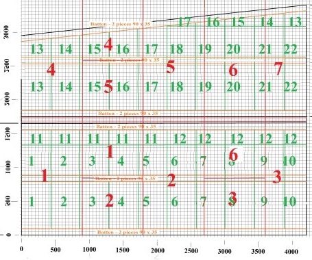
Plywood sheets are numbered in RED.
A similar graphical quantity survey was drawn up for the thermal insulation.

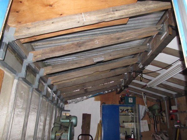
The concrete block side had a temporary roof just for the construction phase. Thus the first permanent roof construction was on the bazza side. This work was done in a rush with no good photographic record. This is how it looked from the inside when finished.

The outside was completed except for the corrugated iron, and wrapped in plastic.
The sequence that has to follow here is that the roof for the other side has to be completed to the same stage. Then both sides can be measured up for the roof guttering and that can be ordered. Then roof guttering can be installed both sides. As the roof guttering is under the corrugated iron, the iron can only go on after the guttering.
The other side has temporary corrugated iron roofing that sits on top of the concrete block wall.
The first job on the second side was the installation of brackets on the ridge beam to take the rafters. In this view, the temporary roof is visible above.
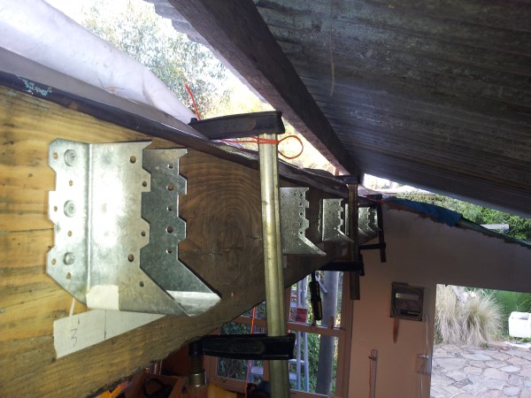
Sockets for the rafters were already in place as part of the steel structure along the concrete block wall, so the placement of the rafters was easy. I "picked the eyes out of" the remaining timbers from the old rails from the Wombat Creek Tramway.
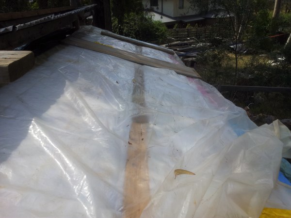
When the plywood is placed on top of the rafters, it has to be nailed down. Seeing where to place the nails is easy: right down the edges of each sheet, and down the middle. The plywood sheets were marked in pencil down the middle for nailing to the rafter that runs down the middle of each sheet. Sarking is placed on top of the plywood, and this obliterates all signs of the locations of the rafters. Thus it is necessary to leave marked around the edges to show where the battens are to go...(the middle batten goes 817 mm from the edge)
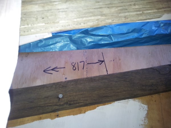
, and where the rafters are so that batten fixing screws can pass through
sarking and plywood and not miss the refters that they are supposed to screw into.
The sharpie marks on the paper flags on the concrete wall show rafter centre line locations.

The plywood sheets were cut and temporarily fitted in place. They were all then removed and painted. They were then slipped back into place, with care not to scratch the paint. This gives a painted cailing with no paint on the rafters.

All this work took place under the temporary roof. The nailing of the ply is not complete. That will require removal of the temporary roof. That will wait unit the battens are ready to fix.
Years ago, I picked up (second hand) some large baulks of douglas fir. The best of these had been selected out and is now the workshop ridge beam. It was now time to deal with the rest. The design calls for the roof battens to be 70 mm thick. On the first side (Baz side) of the roof, the battens were made up with two thicknesses of 90 x 35 pine. That was not completely satisfactory. Thus the plan had been to rip up the big material and make the battens out of it.
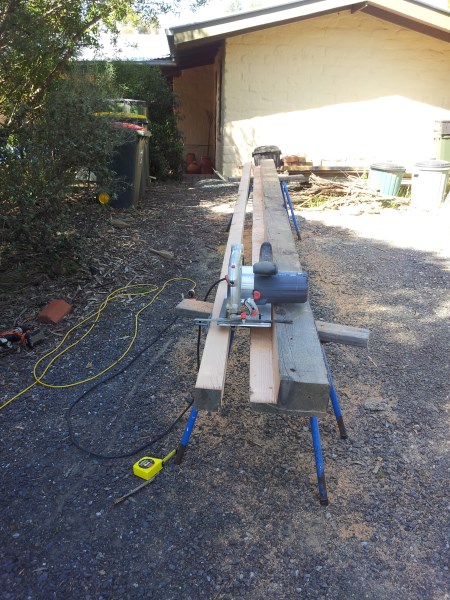
Whilst I was at it, I ripped up the remainder into planks for the door.
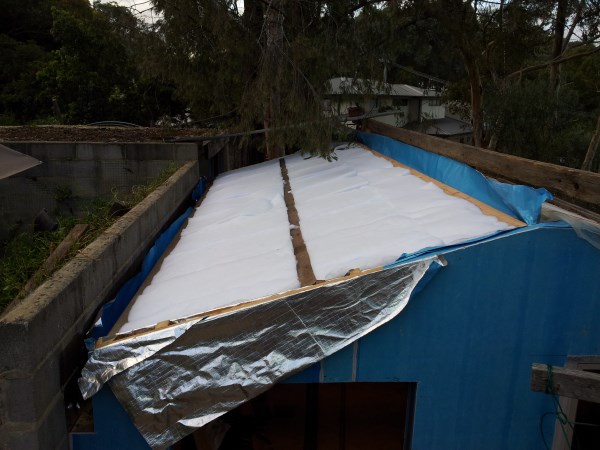
Then the big day came when it looked as if there would be a whole day without rain, and it was time to remove the temporary roof. The nailing of the plywood was quickly completed. Sarking was placed, and then three battens were screwed to the rafters

Although I had found a special saw to cut the 90 mm thick insulation in the walls, the 70 mm thick insulation for the ceiling is especially formulated for acoustic absorption. This stuff has a thermal rating of R1.5, so it still works for us. Unfortunately, the finer fibre used in the acoustic stuff, makes it immune to efforts with the saw. It had to be cut with scissors. It was with a very saw right hand that I took the following picture at the end of that day.
Next: roof gutters. These are complex as there are many constraints on the design of them. All the building elements that will come up against the roof gutters are now in place, so I can draw them up, and think up lots of questions about how to proceed for the sheet metal factory.

This sketch was prepared to show the sheet metal blokes what I am hoping for. I do hope that they are kind to me!