Richard's Workshop
Sheet Metal Parts
Part 2. Roof Gutters and Roof Cladding
In the last report I showed the special provisions on the "jinker" trailer. When this was ready, I asked the sheetmetal shop to go ahead.
.jpg)
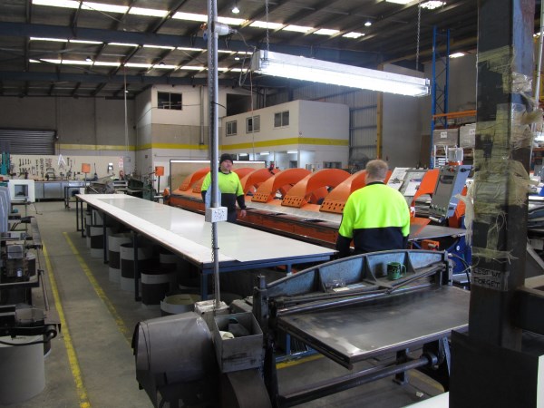
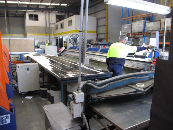
The sheet metal shop was a little different from those I have been familiar with in the past. The material comes in in rolls. It is fed through a small guilotine. The cut length is fed on to a table from where the operators pass it into the machine. As far as I could tell, the machine is both a guilotine and a folder. There were two of these, shown in the following two pictures.
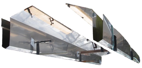
Here are the two roof gutters on the jinker.

In the previous picture, the roof gutters are carried on the jinker upside down. If we hold the jinker upside down, and then edit the jinker out of the picture, we can see the gutters the right way up.
I have been turning over visualizations of these roof gutters in my mind for over a year now, so it is difficult for me to judge just how clearly they are represented. Here is a repeat of a concept sketch of them that I made of an earlier stage. I hope that the similarity between the concept sketch and the reality stands out.
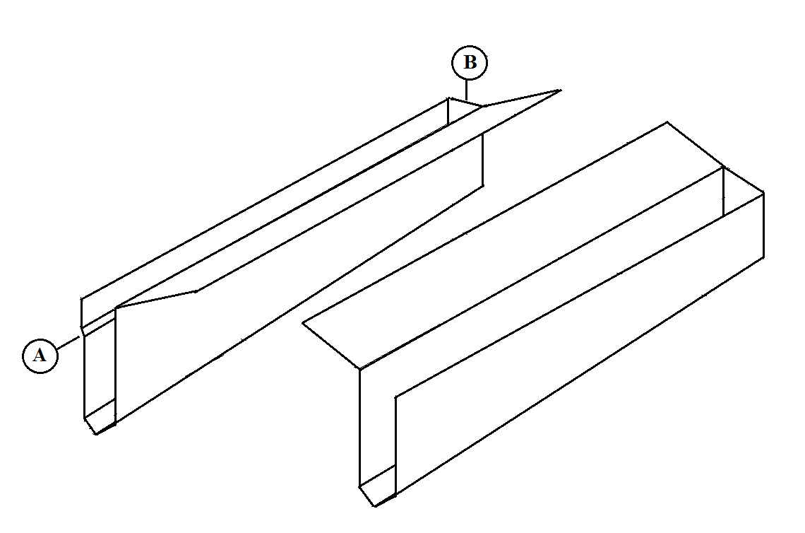
I do not recall whether I have emphasized this before, but I have always regarded the detail of conventional roof gutters that they overflow at the back as really stupid. Such overflowing would be intolerable in this building, of course, as it would be an overflow into the building. I have thus provided each gutter with a wide turnover up on to the roof batten and under the roofing iron.
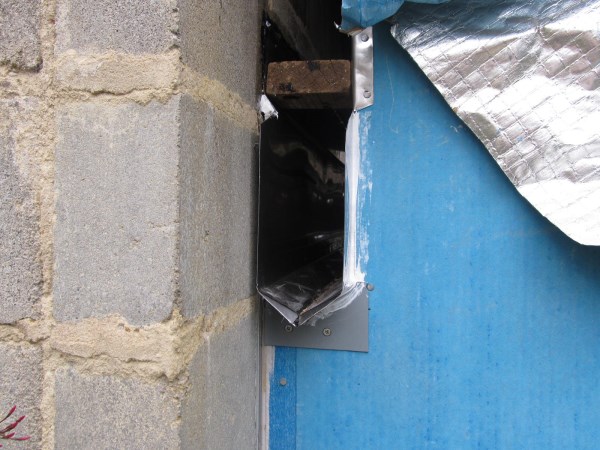
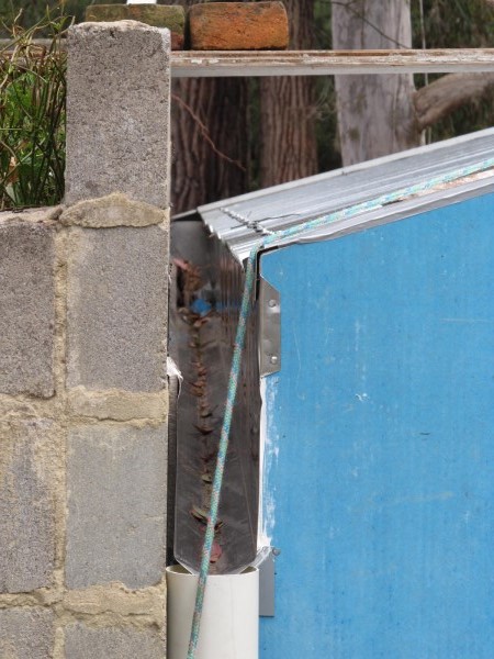
The gutters popped into place without trouble just as if they had been especially made for the application. It remained to finish off the ends of the gutters at the front wall, where they protrude from the wall. here is the detail at the concrete wall side. Note the steel filler piece at the bottom, and that the gutter is sealed to the front wall cladding.
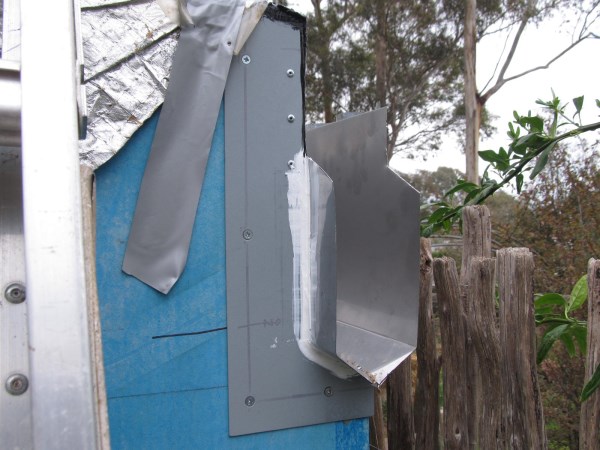
Here is the front wall/gutter detail at the bazza side.
Here is the same spot viewed from above.
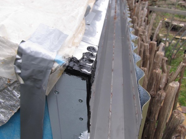
On the concrete wall side, the stainless steel is sealed to the wall with silicone mastic. I did not want to use fasteners here and spoil the clean line. I considered it important that the silicone seal should not carry the weight of the gutter and its contents. Here is a drawing of one of several small jacks that I made and installed to carry the weight.
.jpg)
It was decided to allow the roofing sheets to protrude 10 mm into the gutter cavity. At the concrete wall side, the sheets would be cut square at the bottom (gutter end), so the natural sheet ends were used. The only provision that I had for cutting the sheets to length that I had was a cutting wheel in the grinder. Wherever possible, I arranged the sheets so that the grinder cut ends were up under the ridge cap and out of the weather. I made up a jig to be placed in the gutter that the sheet could rest on and would locate the sheet lower end correctly.
Here is the jig under construction. I have drawn in the top-fold edge of the gutter in blue. The 10 mm extension of the roof sheet into the gutter space is shown in red.
.jpg)
Here is the jig in situe in the gutter.
All the sheets on the concrete block side are of the same length, and all have the lines of fasteners in the same place, as the concrete block wall, the three battens and the ridge line are parallel. The sheets were all cut to length, and marked with lines representing the locations of batten centres for locating screws before the roofing day.
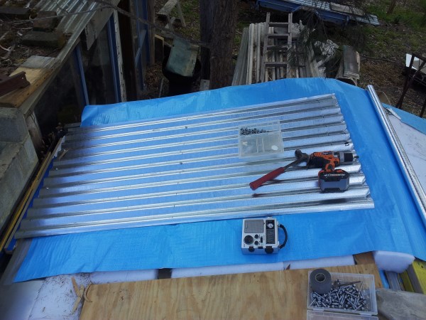
Here is the first sheet to be fixed. Note the plywood in the foreground. On this side, the plywood covered the whole roof, as it was relied on to walk on during the roofing process. Each sheet of plywood was removed just before the corresponding sheet of steel was applied.
Here is a view up the gutter, which shows that this jig did give a fairly straight line to the sheet bottom edges. The marking out of the sheets beforehand also gives a satisfying straight line to the fixing screws.
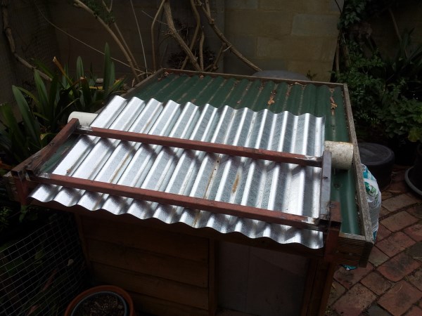
On the Barry side, the gutter line is not at right angles to the line of the fall of the sheets. They thus have to be cut at an angle at the lower edge. A completely different jig was called for here. This is a marking out jig. This jig consist of a steel frame that sits on the temporarily installed roof sheet. It has two fingers that reach down into the gutter and press against the gutter wall. It is shown here sitting on top of a dog kennel.
Here it is as it would be seen looking along the gutter. The gutter is drawn in in blue.
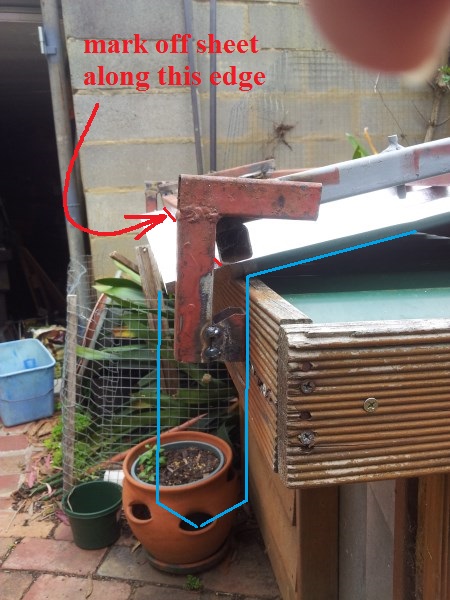
The process here was that each sheet was placed temporarily and fixed with two screws at the ridge. The jig was then placed, and a line drawn on the sheet representing 10 mm protrusion into the gutter. The sheet was then removed and cut to length down on the ground and then reinstalled.
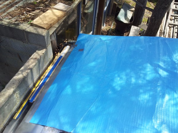
Here is a picture taken during the day when all the concrete block wall side sheets were installed. This is the fist day for many months when there was no "temporary roof" installed at the end of the day.
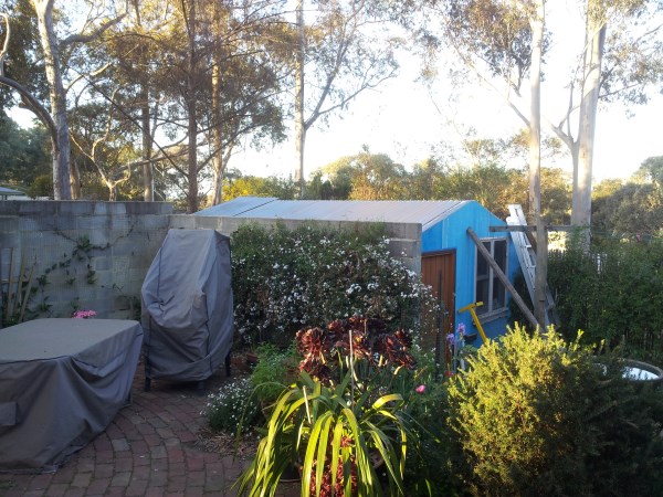
After the gutters were installed, a collection of leaves accumulated in them. Just after completion of the roof iron installation there was a heavy rain shower. The leaves were all rinsed out except for a pile at the uphill end. The self-cleaning feature is a success. You can't beat 100 mm fall in a 4 m long gutter!