
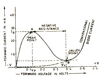
I remember that when I was a youngster, my grandmother commented that “they” were saying that transistors would take over from valves. I reported that I had read in the magazine “Radio and Hobbies” that the transistor was predicted to be taken over by a new device called the “Tunnel Diode”. The tunnel diode dates from 1958, and was in production in 1960. It earned its stripes as an active device, even though it had only two leads, by having a “negative resistance” region in its voltage/current characteristic.
Exploiting or avoiding negative resistance regions had become well established in valve (vacuum tube) days. I had read many explanations of the history of growth of the number of grids in the thermionic valve. The explanations (or was it my youthful, impatient eye) seemed to gloss over the number two. We went from triodes to pentodes, with a very scanty look at tetrodes. There was mention of secondary emission and negative resistance with tetrodes, but these notions were quickly glossed over.
The Radiotron Designer’s Handbook (mine is 4th edition; 1955 but this matter might not have been revised since the first edition in 1934.) mentions secondary emission from the anode in a tetrode (pp7) but in that section does not mention that this can give rise to negative impedance at the anode. In the chapter on oscillators, there is mention of a “Negative transconductance oscillator”, but the design described does not utilize the negative impedance of the anode in a tetrode. (The Radiotron Designer’s Handbook might not be considered children’s reading, but nevertheless, I wish the Father Christmas had been on to it in the early ’60s.)
I remember one construction article in which tetrode characteristics were wanted, and this was achieved by selecting a pentode in which the suppressor grid was connected to a separate pin, rather than connected internally to the cathode. Youngsters who are not familiar with this talk and are interested might like to check the Wikipedia article (http://en.wikipedia.org/wiki/Vacuum_tube) on this which is mostly good stuff, and very little piffle.
I remember a discussion amongst juvenile philosophers at a railway volunteer work party in which we discussed negative resistance, but dismissed it as impossible as it implied that the device was a source of energy. We had not learned to distinguish between E/I and dv/di.
Negative resistance characteristic of tetrodes was exploited in trigger circuits, which could be configured to “snap” between stable states if set up so that the negative resistance region imposed an “S” bend over the load line.
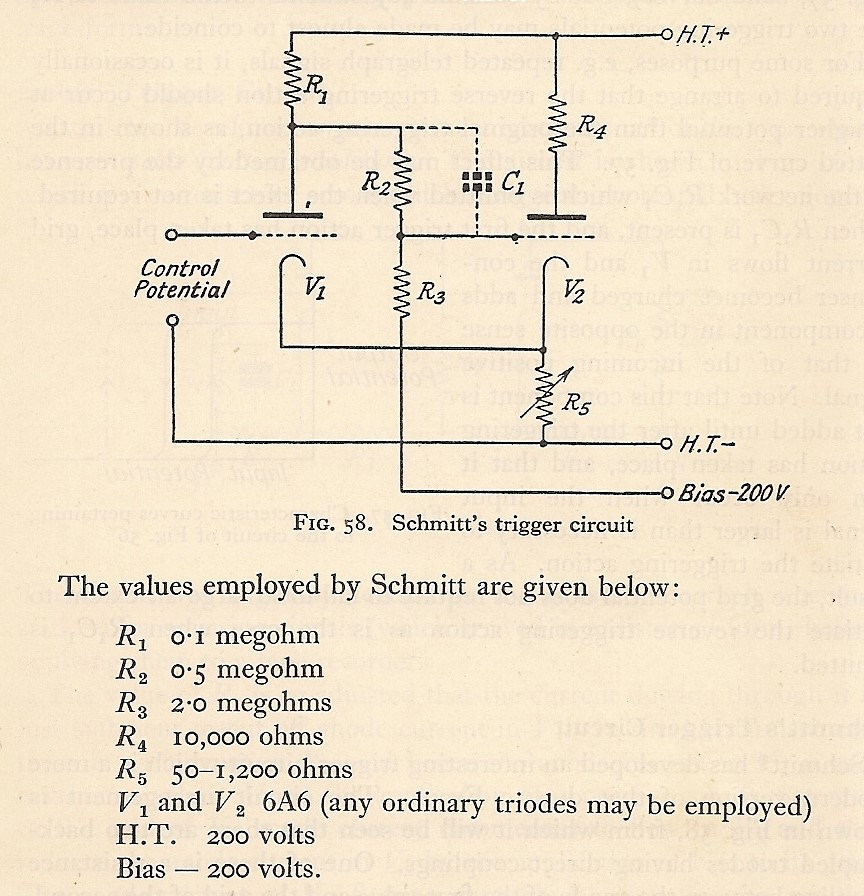
In his book “Time Bases” (1943) Puckle gives several examples of peculiar bias arrangements of tetrodes to obtain a characteristic curve with a negative resistance region in it. The earliest citation for a work describing ways of obtaining negative resistance was from 1935. The motivation in those days was the ability to build a trigger circuit with only one valve. There were many two valve trigger circuits in those days: one of course being the well known one by Schmitt which used two triodes. Schmitt’s trigger had particular features that distinguished it from the several alternatives available to the designer in those days. These features are mostly absent from the arrangements of positive feedback around a comparator or op-amp that is commonly called a Schmitt Trigger today.
The motivation to “use only one valve” must have been very strong in the days when a valve cost about £1/-/- and the average weekly wage was about £20/-/-. This would put its cost in today’s (2014, Australia) money at about $29.00.
One circuit used the MS4 tetrode.
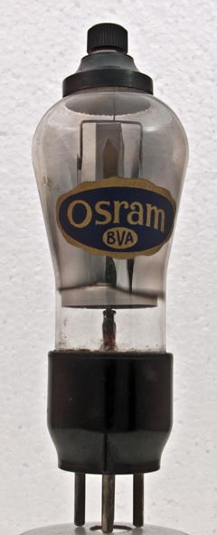
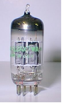
This MS4 Valve picture is from the National Valve Museum http://www.r-type.org/exhib/aaa1359.htm. This motivation to use tetrodes in this way was overcome by the introduction of integrated circuits, although we didn’t use that term then. The trick was to put two triodes in one bottle. A Schmitt Trigger could then be built using “one valve”.
Two triodes in one bottle. Enabled a Schmitt’s trigger to be built with “one valve” and killed the tetrode “negative resistance” trigger.
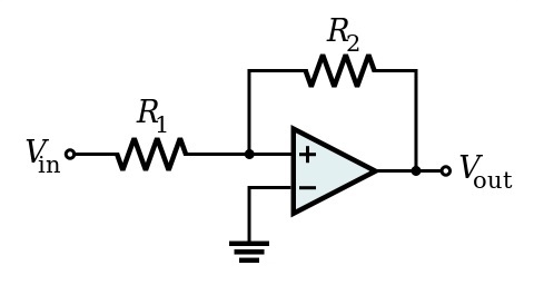
As an aside, in modern circuitry, we could be justified in calling this:
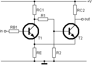
a Schmitt Trigger, but not really this:
In spite of the fact that this circuit comes from the Wikipedia page for “Schmitt Trigger”, it owes nothing to Scmitt’s circuit. It is a lost cause, but it would have been better if such a circuit were called an “hysteretic trigger’ or just a “trigger”. (Sigh!)
Note that the transistor circuit (above) seems to have been derived from Schmitt’s two triode circuit without much thought. It will generally be found that the VCE(SAT) of the first transistor is less than the VBE of the second. R1 and R2 are thus both unnecessary. Replace R1 with a short, and R2 with an open circuit.
This negative resistance business is important in modern electronics engineering. I gave an example in my post number 14 “Is a skim across the top worse than no analysis at all?” and number 15 “Load Line” (both October 2013). Another example arises in the use of a resistor for “soft start” of a switched mode supply. I might treat this in another post. I will finish this post with a last blast from the past.
For a recent post, I was looking up M. G. Scroggie (“Cathode Ray”)
http://en.wikipedia.org/wiki/M._G._Scroggie
and I came across this delightful conundrum.
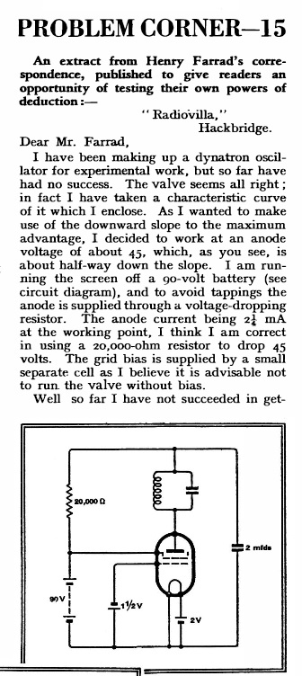
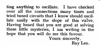
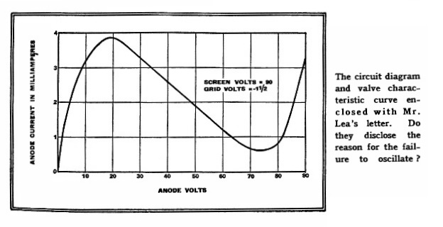
I will leave this hanging in the air just for now. I will give my explanation for Mr Lea’s problem next post. In the meantime, I offer a packet of Smarties for the best reader’s solution.