
33 Negative Resistance Part 3 in which I realize that we need to distinguish between the negative resistance of a component and the resistance of a circuit. Maybe the solution to the tetrode oscillator problem was easier then it first looked. I also expose (but do not solve) a mistake I have made.
Last time I showed that the tetrode negative resistance oscillator, that would not work from a 90 volt supply with a dropping resistor, would work ok with a low impedance 45 volt supply. See earlier posts.
Later I realized that it had not been quite correct to say that the oscillator would not work with a 90 volt supply and a dropping resistor. In fact the originator of the circuit had been quite wrong when he complained that it would not work. It would work all right, it just would not start! This can be shown by starting it with a low impedance supply and letting it continue to run with the dropping resistor.
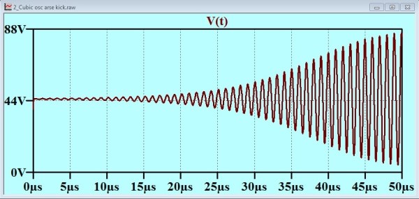
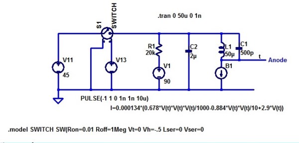 This is what I call my “Kick in the Arse” circuit. It starts off with the switch closed. This provides a low impedance 45 volt supply to establish 45 volts on the 2u cap C2. The oscillator starts. Then the switch opens, and the oscillator continues to operate perfectly well with what amounts to the original circuit!
In fact it would have been much more easy than this to provide the required “starting kick”. Consider this circuit:
Of course, there would have had to be a power switch, or probably two power switches, as it would have been necessary to heat the cathode before applying the starting kick. Again, (in simulation) the oscillator starts and runs.
We might wonder if the simulation model is too “ideal”. A real 90 volt battery would have some series resistance. It might also have properties that dictate that it is not good practice to create large transient currents by placing a microfarad directly across it. I have tried placing a resistor in series with the supply. This resistance can be as high as 1k and the oscillator will still start. You can regard this 1k as modelling the battery intrinsic series resistance, or as an imposed surge current limiting resistor, or you can share the 1k amongst these concepts. It all depends on your line of thinking.
To further drive home the distinction between the negative resistance of a component and of the circuit as a whole, I set out to check the power supply input characteristics of this circuit. First, I tested my oscillator circuit model, and determined that it would start and run with a supply voltage range that exceeds 25 to 50 volts.
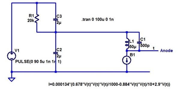
Then I set up a model to see how the supply current varied with supply voltage over this range.

The current source and the capacitor C2 provide a voltage ramp. The voltage controlled voltage source E1 follows that voltage and provides current that will not interfere with the current in C2. The resistor R1 has been included to allow C2 to present the lowest impedance shunt path for the oscillator signal. This enabled us to plot the output current of E1 with minimal high frequency ripple.
Let us limbo dance under the barrier to high frequencies presented by the capacitor.
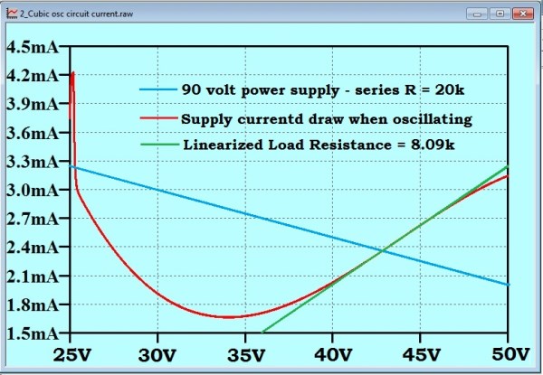
I have relabelled the x axis to show the variable supply voltage, instead of the time, which was the true independent variable in the simulation. The red line is the curve generated by the simulation. The “spike” at the left side, is, I believe an artefact of my start-up transient. Indeed, although I cannot slow down the whole sweep very much, as the simulator is generating data for every cycle of the oscillator, and attempts to run the sweep very slowly lead to the generation of files that are too large for LTspice to handle, I can do a slowed down simulation of just the first couple of milliseconds of the sweep. If I reduce the sweep rate, the height of that initial current spike is also reduced.
The green line is a tangent that I have added by hand to determine the dynamic resistance of the oscillator as a load on the supply. The blue line is the load line for a 90 volt, 20k supply. It is evident that the operating point is completely stable. Note that the operating point is not at exactly 45 volts, but about 43 volts. That is not skin off anybody’s nose.
The ‘split capacitor circuit that I showed above, (repeated here to save you looking back)
exhibited a characteristic for the first 100 μs like this:

The brown trace is the tetrode anode, and the blue trace is the junction of the two 2u capacitors. It occurred to me that if we run that blue plot for a longer time, we should see it sink to about 43 volts, the stable “operating point” that we determined with the load line above. I did the simulation, and this is what I got:
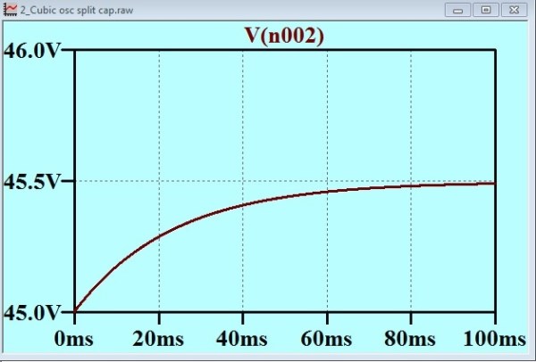
You can see that the quiescent point for the junction of the two 2u capacitors is about 45.5 volts. I cannot see how this can be different from the operating point we found with the load line (above). Can you?