Posted 25-03-2018
This post is made up of old material. It had been stored away in several emails that I had sent off years ago.
Last night I had dinner with an old electronic engineering friend. Several interesting points came up in our discussion, and in many cases, I was able to refer to a post in this blog where I had expanded on the matter. (It was George Bernard Shaw who wrote “I often quote myself. It adds spice to my conversation.”) There was one exception: and that is the subject of this post. So…. here it is, out of the shadows and where I can refer people to it.
This post does not expand on some technical matter for my engineering peers. I expect that the general thrust of what I write here is already known to you.
It all started at a different dinner party. NOT a gathering of engineers. One fellow was expanding with raucousness and passion on why he hated digital audio. As he described the quantization process, his face screwed up as if he was being forced to sniff fresh dog shit. I took the view, and I still do, that engineers had put in a lot of work developing modern audio systems, and for a person who does not understand any of the issues at stake, and to give priority of his baseless opinion over the development work of many people who had gone into the design problems in a lot of detail IS OFFENSIVE.
I “blew my top”.
Later, I tried to be a little constructive with what follows. I took a two pronged approach. One was an “in principle” approach, and the other was a report of actual results.
Prong 1.
Here is a (slightly edited) version of what I wrote over several emails.
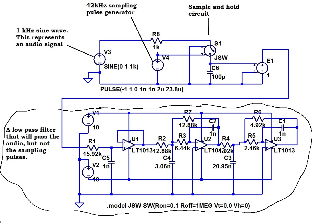
First, I did a little circuit modelling.

This circuit model (I explained) is to generate some demonstration signals. This circuit takes a 1kHz sine wave, samples it at 42 kHz (A sampling frequency, I believe, that is used in digital audio) and then limits the frequency content to that that is discernible to human ears.
This is the sort of situation in which one could easily get buried in detail. This sampler samples the signal in time. I have not introduced the complexity of quantizing it in voltage as well. I just left out any attempt to present some maths to justify this, as my reader would not have appreciated that. He might not have understood the distinction between quantizing in time (sampling) and quantizing in voltage.
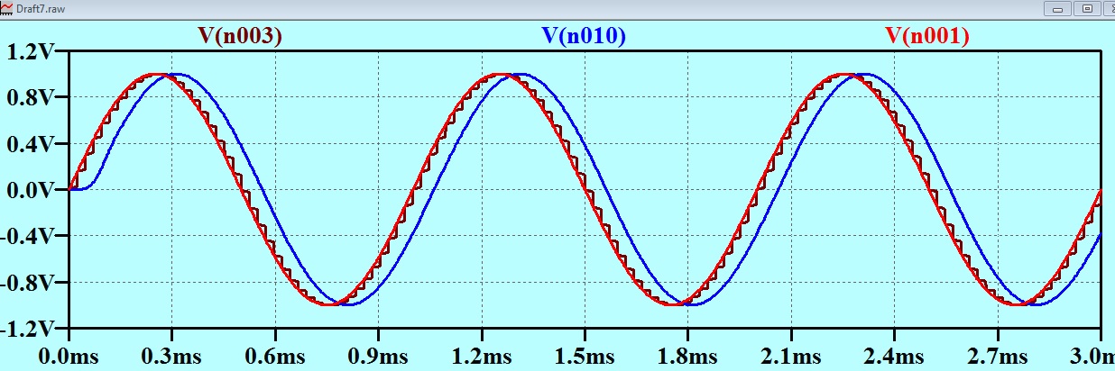
The red trace is the original audio.
The brown trace is the digitized audio.
The blue trace is the result passed through the low pass filter.
The thing is that NO ONE can tell the sound of the blue trace from the sound of the red trace.
In a following email, I covered myself a little for simplifying the matter as follows:
I have been thinking a little more about what I sent you earlier. I was trying to be helpful, but the task is really very difficult. It would REALLY NOT be helpful to you if I said that you needed an electronics degree to understand, or to set up tutorials to cover the material to the same level of detail that brought you up to electronics degree standard. So I have thought up a much simplified model to demonstrate the point.
You need to be aware that what I have done is DEMONSTRATE the point: not PROVED it.
If you were to focus your attention on the simplicity of my model and search for weaknesses in it, I could counter every discovery of weakness that you made, with the addition of complexity to overcome that weakness, and we could continue that process until our correspondence had almost amounted to a degree in electronic engineering by correspondence.
However, there is a little I want to add the the exegesis of the simple model so as to make the point clearer.
In the above trace of the output of the circuit that is quantizing the signal in time (brown) and the signal at the output of the filter, which I have previously identified as indistinguishable from the original signal (blue)
You will notice two things about the blue trace:
1. The “stepiness” is smoothed out.
2. The blue trace is offset a little to the right. This means that the blue trace is delayed by about 100 microseconds or so.
You will see that the delay doesn’t matter at all, as it can be completely overcome by just starting the playback of the recording 100 microseconds earlier!
The original sine wave signal had an amplitude of 1 volt. (2 volts “peak to peak”)
The 135 mV peak to peak of the “steppy” artifact corresponds to an amplitude of (roughly) 70 mV.
This is 1/14.2 of the amplitude of the incoming signal.
This is at a signal level of – 23 dB with respect to the incoming signal.
We can observe that the filter appears to “smooth out” the “steppy” signal. However it is actually wrong to characterize it this way. If you were to print out the “steppy” line, on a huge piece of paper, you could draw a line that appeared to “smooth” it out, but then again, someone else could draw a slightly different line which also represented a “smoothing” out of the steppy line.
The line (blue) is actually a VERY SPECIAL case of “smoothing out”. It is the case where all the high frequency components have been (for all practical purposes) removed.
Remember that I just chose this particular filter design to make a simple point. If you were to complain that it does not filter enough, then I can increase the filter performance WITHOUT LIMIT, so, in this way I can eliminate that objection, so don’t go there.
The filter I have chosen is just to be illustrative.
The graphs that I have sent you are said to be in the “time domain”. The horizontal axis is time. An alternative way of looking at the same thing is to look at the frequency domain. It is conventional (and with good reason, that is outside the scope of this email) to do this with log log axes.
Here is a representation in what we call the “frequency domain”

In the graph above, the dark line line is the filter performance.
I notice that I had chosen a filter with a 10 kHz corner frequency. This could give rise to an objection. I will work out how it looks with all the high frequency stuff 30 dB stronger as they would be with a 20 kHz filter.
The red line represents our demo test signal.
The green lines represent the “steppiness” in the frequency domain. I have drawn them in by hand. The green lines continue on, to the right until the point is reached where they have gone down below the sort of “electron per fortnight” current levels, and you are into quantum physics.
If you look at the first green line, you will see that it is -65.3 dB with respect to the signal. However the “steppy” signal was already at -23 dB with respect to the signal, so the steppiness comes out to be at (-23)+(-65.3)dB = – 88.3 dB. This is certainly below the noise and undetectable, but as I said before, If you want it to meet some stricter criteria, I can extend the filtering WITHOUT LIMIT.
Another way of looking at it, is to say that the filter separates everything to the left of the purple line from everything to the right of it.
It turns out that your ears do this filtering for you and for nothing. That is, if you were doing ABX tests and there were ultrasound transducers in the room putting out the green line signal, you could not detect them. However there IS still a good reason for doing that filtering. That is that if the filtering is not done, then the presence of the out-of-band signal could degrade the performance of the electronics between the D to A converter and your ear.
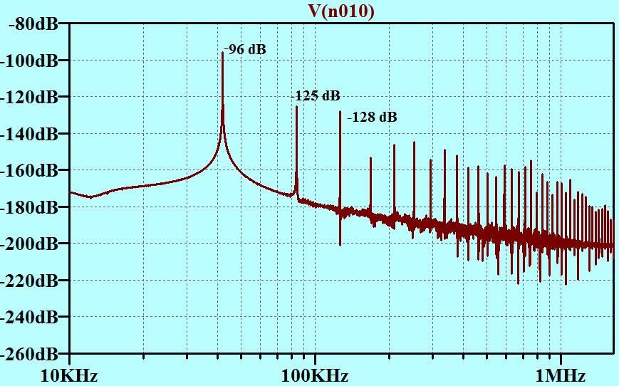
Since that correspondence took place, I have looked into this a little further. The sampling noise will be a saw tooth waveform, but the polarity of it depends on the sign of the slope of the signal. and the magnitude on the steepness of the slope. In real life, it will have sidebands! Let us assume that it is a constant amplitude sawtooth with a peak to peak value of 135 mV. Is this a worst case”?
I have extracted the level of the first three spectral lines from the simulator and added them to the plot. Note that the voltage levels in the simulator FFT package are dB re a volt RMS. Our imagined signal was 1 volt amplitude which is -3 dB on the above scale.
|
Smpling Noise spectral lineFrequency |
Level re 1 volt RMS |
Level re 1 volt amplitude sine at 1 kHz |
Level re 1 volt amplitude if the filter corner frequency had been 20 kHz |
|
Fundamental |
-96 dB |
-93 dB |
-63 dB |
|
2nd harmonic |
-125 dB |
-122 dB |
-92 dB |
|
3rd harmonic |
-128 dB |
-125 dB |
-95 dB |
Note that the -93 dB figure in this table is 4.7 dB different from the figure arrived at (above) following different assumptions. I am not going to attempt to track the origins of the differences. The assumptions are very crude to start with. My point is made without having to resort to a precision as fine as 4.7 dB!
If a person such as my correspondent reckons he can hear that sampling noise, he is having a wank. He needs to get a good solid ABX test up his jacksie. This brings us to:
Prong 2.
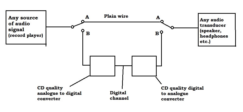
Remember that this is NOT about record players vs some other sound reproduction system. The statement I was making was all about CD quality sound. It does not apply to MP3 quality sound.
A person can listen to the music with both switches in the A position, in which case digital audio doesn’t come into it. The same person can listen to the same music with both switches in the B position in which case, the analogue signal is converted to digital and then back to analogue again. The thing is, it is not possible to hear the difference. Very well documented.
There is actually no information flowing up the wire to the speaker or the headphones that could be utilized to discriminate.
I found the following for my correspondent.
http://www.bostonaudiosociety.org/bas_speaker/abx_testing2.htm
Lipshitz and Vanderkooy are both audio equipment designers. I think that Lipshitz is an electronics engineer. Vanderkooy is a physics professor in Canada.
My correspondent did respond to my emails, but in his responses, he only addressed “Prong 2”. The substance of “Prong 1” was not to his taste. Do you reckon that a person who will not make the effort to get his head around this stuff, is entitled to an opinion about it?


Since the 1980’s, the vast majority of music recordings have been digitally mastered, so if you harbour some superstition that a recording is somehow degraded by being sampled digitally, then you’re stuck with it. Never mind, we can still enjoy the distortion, tone coloration, noise, wow and flutter of vinyl recordings, preferably played through a vacuum tube amplifier with a microphonic pre-amp.