Towards a Temperature Compensated Current Source.
Second Post on Topic
17-05-2013
Synopsis.
I continue to look at current sources for an application in which the temperature coefficient had to be kept under control. This post assumes that the reader has read my previous post on this subject. If you have not read that, seek it out before reading this.
Requirement
The application is a pulse width modulator in which a fixed current is applied to a capacitor to provide a “time – voltage” relationship. The application does not require very high accuracy or linearity, but a couple of set points on the range (min and max) have to stay pretty well where they are put. (Just exactly what “pretty well” means is not determined yet.)
There are two ways from here
The narrative splits into two at this point. I will have to deal with them sequentially. When you get to the second branch, just remember that this is where it branches off.
Current Source Thread Branch 1.
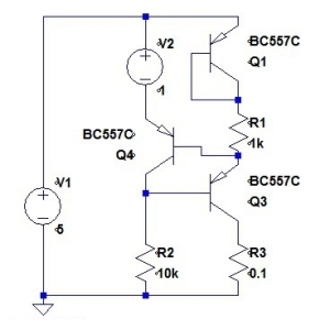
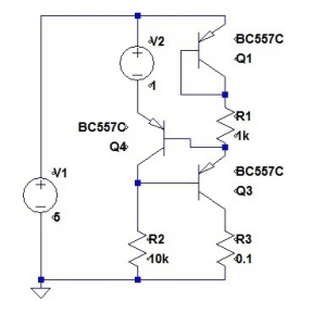
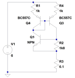
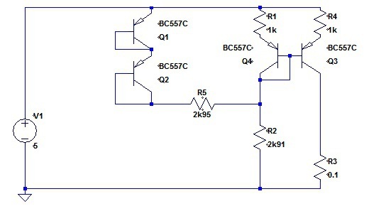
Just a reminder, this is the current source circuit that I had at the very end of my last posting.
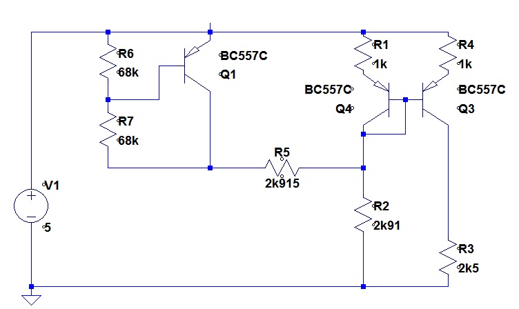
On simulation, this yields output current from 0.99954mA to 1.00026mA over temperature: a change of 720nA. (The temperature range I had selected for these tests was 0 degrees C to 70 degrees C) The actual sequence that lead to this circuit was not exactly as I had stated in the last posting. I had been tweaking the values of the resistors R5 and R2 and found that my optimum was at almost identical values before the reason that they would be almost identical became clear.
By the time I was writing out the last posting, it was obvious why:
(a) They are almost identical
(b) Choosing the same value in “real hardware” would be near enough
(c) The optimum values I had found by iteration in the simulation were not exactly the same.
Just to clarify in my own mind exactly how the temperature compensator was influencing the mirror, I went into the matter in a little more detail. Some of you will be way ahead of me, but others might find this clarifying.
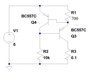
Here again is the raw current mirror.
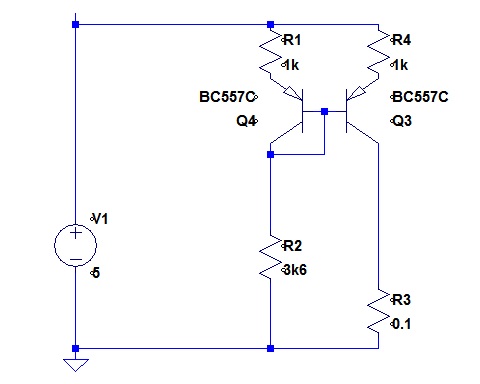
Remember that I had identified that the main temperature error (assuming identical transistors) arose because the current in the left branch has to traverse:
(a) R1
(b) VBE of Q4
(c) R2
As the VBE of Q4 varies with temperature, the volt drop left to share between R1 and R2 changes, and thus the current changes. The temperature compensator replaces R2 as a current sink for the Q4 collector.
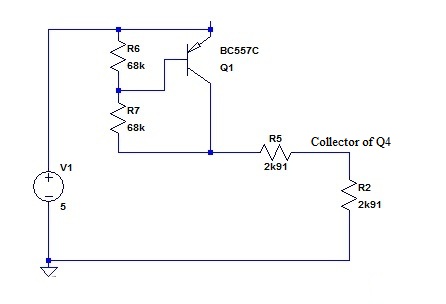
I like to show voltage dividers as voltage dividers, and a change to this yields:
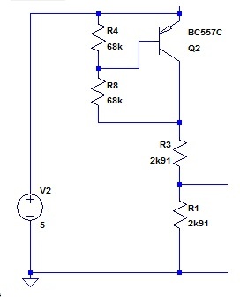
Replacing the VBE multiplier with a voltage source symbol changes the circuit to:
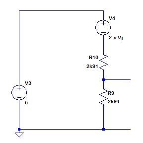
The voltage source V4 has a magnitude of output of two times VBE. Notice that I called this 2 x Vj (for Voltage of junction) as the circuit capture on the low price spice does not provide for subscripts.
It should be noted here, that there is nothing, as far as I can see, that is magical about the number 2. This circuit would work if V4 gave 1.8 times the junction voltage and then the voltage divider divided by 1.8. Indeed, there might be some reason for choosing a number other than 2, but I am not going to pursue it in this posting (see below).
When we encapsulate the voltage divider in our model, we get:

The voltage source is halved, and the output resistance is the resistance of the two divider resistors in parallel. Now let us reunite the temperature compensator with the left leg of the mirror.
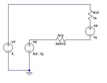 There are three voltage sources in series around this loop. Lets incorporate them all into one.
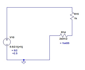
The voltage across the resistors has no contribution from any junctions within the limits of all the assumptions, stated and implied.
My third obvious point above, (c), was that it seemed obvious to me why I had found an optimum in which R5 and R2 were not exactly the same. I reckon that it is because the junction that has its volt drop multiplied in the VBE multiplier is not carrying the same current as the junctions in the mirror. I have observed that we can multiply, and then divide this VBE by some number other than 2. I reckon that in this way we could change the current in Q1 so that it matched that in the mirror transistors. Some tricky maths might yield a simple answer that would give us different resistor values and a better optimum. I am not going to go there now for two reasons. First the optimum is pretty good already, and second, this is the place to terminate this branch and go back up to the branching point and look at the other.
Current Source Thread Branch 2.
After I had posted the last posting on this, I was looking a bit further on the web and I had one of those “D’oh!” moments. (Is that how you spell it?)

I found a circuit that was simpler than the one I have developed above and which will most likely be good enough. It reduced the transistor count from 3 to 2. I do not remember ever seeing it before, but that is no excuse. As soon as I saw it, I could see that it was so obvious, that not thinking of it was inexcusable. I will record that I had several replies to the last posting, and one of them was on to this (after I had found it). The circuit was in a group of images that Google offered me when I Googled “Temperature Compensated Current source”. I tracked it down to:
http://www.radio-electronics.com/info/circuits/transistor/active-constant-current-source.php
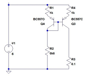
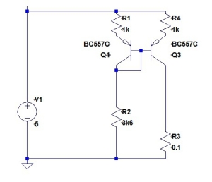
… a site I do not particularly recommend, as it is written at too simple a level for readers of this post. Their circuit was:
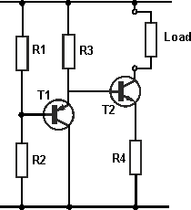
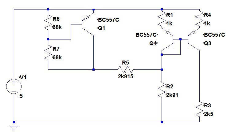
As I wanted a current source and not a current sink, I took the simple step of turning it upside down.
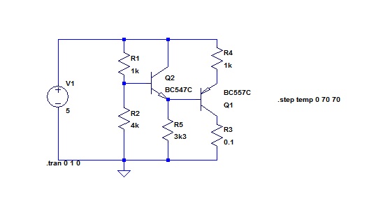 The operation is obvious: (to a first approximation) the constant voltage determined by the divider R1 and R2 has one VBE subtracted from it, and then a VBE added back to it. The two VBEs can be contrived to match reasonably well if the two transistors carry the same current.
This arrangement was adopted in my circuit. I had described the requirement earlier, but I should perhaps add that this circuit is for publication in a hobby magazine, and might go on to be constructed by a number of amateur constructors. The optimum economy in the design will thus be different from most design projects. In particular, the product cost is the BOM cost. Labour is costed at zero. Secondly, component availability is an issue. One lot of freight cost from Digikey will buy a lot of parts from Altronics or Jaycar when the purchasing is being done for a production run of one. This is why I have not chosen one of the monolithic current sources.
Here is my back-of-the-envelope sketch of the module incorporating the current source (as drawn before I went off on this “minimizing tempco” quest).
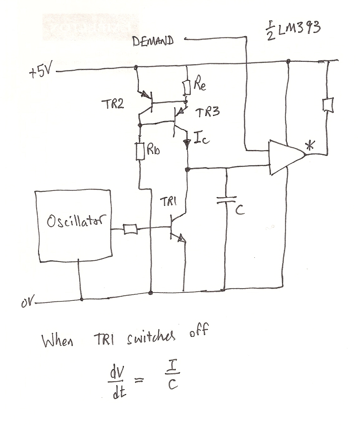 In this application, a “servo” of the type that is used in model aeroplanes and the like is used to activate an engine throttle. The reason that I had written earlier that “couple of set points on the range (min and max) have to stay pretty well where they are put” was that these are the stops in the throttle linkage travel. I place “servo” in inverted commas as in this context the word has come to have a quite different meaning from that used elsewhere. These little jiggers take as input a pulse train, and adjust their position according to the width of the pulses. The requirement to drive one, then, is a repetitive variable pulse width. Here is the circuit a little further down the development track.
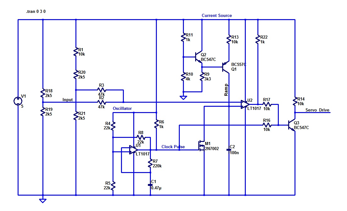
For reasons that are logical, but which I will not go into here, this circuit has some anomalous resistor values showing. If the dual comparator is changed from a LT1017 to an LM393, and the MOSFET changed to a 2N7000 (both changes will have no impact on operation) then the requirements about component availability are met. I only have two line thickness for the reproduction of the circuit above, and I have chosen “thick”. This makes the comparator symbols very unclear. To help you read the circuit: the inverting input is at the top and the non-inverting below it.
Here (in simulation) is the “Servo Drive” and the “Ramp” signal.
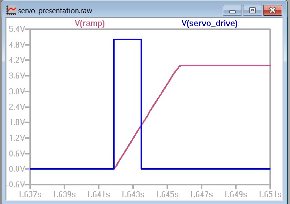
The timing of the falling edge of the output pulse (blue) is determined by the voltage on the ramp.
R.


