
HYTECO DRIVERLESS TRACTOR SYSTEM MODEMS 14-09-2016
It has been some time since the last post, so I will reiterate the background to this one. The context is a requirement for two way communications between driverless tractors following a wire guidepath set in a warehouse concrete floor. In the last post, I discussed the traffic from the central controller to the tractors, which we called “down” traffic. As the carrier for the data signal could be of large amplitude, the only limit being that it did not interfere with the tractor guidance system, we had no trouble getting the signal up out of the noise. We used frequency shift keying using off-the-shelf PLL chips. The frequency deviation was determined by the chip manufacturers. It was not ideal for our purposes but it worked. This was all described in the last post.
In this post I turn to data traffic from a tractor to the central controller (“Up” traffic).
The tractor transmit antenna was designed by Roger Riordan. I have described this in this blog before (“Time Passes 1” posted in August 2013. You can find it easily by placing “Riordan” in the search box.). This was a second attempt: the first was an un-tuned transmit coil driven by a square wave at carrier frequency. This was unsuccessful, and could probably have been made successful, but when I called Roger Riordan in, he wanted to do it “his way” and I (wisely) let him meet the requirements in whatever way he liked.
He chose the Class C output stage with his clever tuning scheme. There was a potential problem with the idea of a tuned antenna. A portion of the magnetic circuit was through the concrete floor. We had discovered that at the sorts of frequencies we were dealing with, the permeability of concrete is much higher than μ0 and varies between concretes with different aggregates. The tractors had to work over the floor of an old building and a new building, so the tank circuit antenna might have detuned a bit as the tractor moved from building to building. It was fortunate that we didn’t waste time worrying about this, as that would have just wasted time. I realise now, as I am writing this about 38 years later, that the difference in the different concretes might have caused a problem that we faced – and then solved later on.
Riordan’s choice of a Class C stage with tuned tank came after my decisions about modulation scheme. The Riordan antenna design does not have the bandwidth to carry the FSK type of signal used for the Up traffic.
I had been concerned about bandwidth for a completely different reason. The receiver had to pick out a small signal from a channel with other large signals on it. One aspect of our efforts to find the signal in amongst all the noise was to place the signal in a quiet place in the frequency spectrum, and use no more bandwidth than necessary. The FSK encoding used for the Down traffic had to use much more bandwidth than the theoretical minimum, as the characteristic relationship between frequency and voltage at the phase locked loop chip VCOs, and the need for voltage swing dictated a large difference between the frequencies representing mark and Space. A different scheme was called for.
When the signal is weak, and of narrow band, it become important to synchronize the transmitter and the receiver. The scheme chosen was to use frequency synthesizers clocked from the guidepath signal at the Tractor and at the receiver and place a phase modulated carrier at 2.5 times the guidepath frequency. The choice of two and a half times seemed to maximize the frequency difference between the signal and the guidepath harmonics. I seem to recall that experiments showed that we had about 100mV of signal at the central station receiver, but we wanted to allow for a worst case position (physical position of the tractor) where the signal was very much weaker. I believe that we had a particular value in mind for tests, but I do not recall what that was. That the communication actually worked in the real warehouse was, when it came to it, a more important test.
The task of designing a suitable receiver was a daunting one. It had to be made according to a robust plan, and that plan had to be executed intelligently with carefully chosen details.
I mapped out a plan for a double conversion receiver. I perceived that analogue filter design was a weakness in our team, (There was no spice, or filter design programs available for running on your pc in those days. There were no pc’s!) so I came up with a scheme that relied on filtering with anything so complicated as conjugation of poles, to an absolute minimum.
The block diagram of the receiver in a later form is shown here.
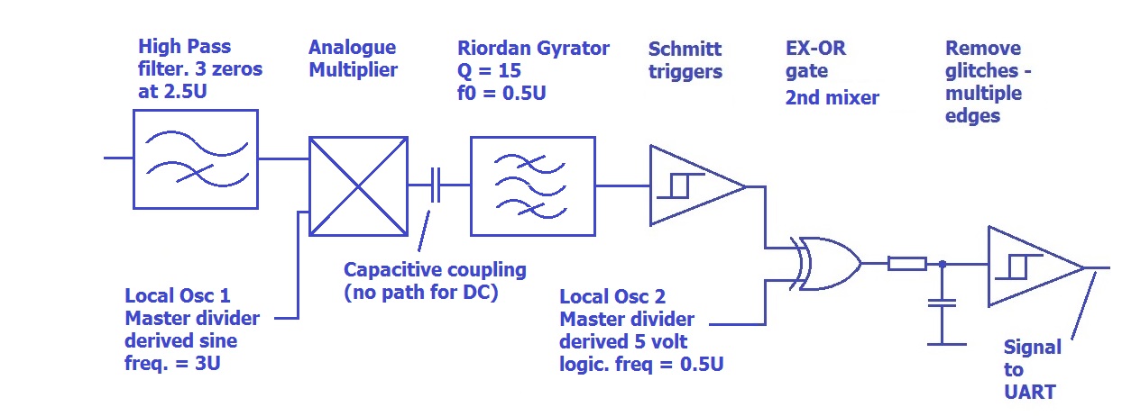
The plan was to use phase inversion keying (phase shift keying where the phase shift is 180 degrees). The source of carrier was a phase locked loop locked on to the guidance signal. The modulator was an exclusive OR gate.
I set up project nomenclature for frequency in which the guidepath frequency was nominated ONE frequency unit (“1U”) and the data carrier, 2.5U. The actual frequencies were 6.25kHz for the guidepath, and 15.625kHz for the carrier.
At the receiver, the first stage was a very simple high pass filter to boost the carrier to guidepath signal ratio. These have a ratio of frequencies of 2.5 which is about 1.3 octaves. Three zeros can give us (6dB per octave each) about 23 dB of preference of carrier over guidepath. For the analogue multiplier, I selected a Motorola part containing a Gilbert Cell (https://en.wikipedia.org/wiki/Gilbert_cell) (designed for use as an RF mixer) as an analogue multiplier to be the first mixer. The signal at the input to the first mixer could not be fed through a trigger, as there were expected to be more zero crossings due to the guidepath and its harmonics than from the carrier itself. The first local oscillator (LO) was at a frequency of 3U, giving an IF of 0.5U or 3.125kHz. The output from the first mixer was capacitively coupled to subsequent stages, giving a very satisfactory and very deep notch in the passband at zero frequency. Interfering signals from the third harmonic of the guidepath are at zero frequency here, so we get a lot of filtering out of a single capacitor just by carefully choosing the local oscillator frequency.
The next step in the block diagram is a bandpass filter utilizing a Riordan Gyrator. This was not part of the original concept plan and was not required according to my signal budgeting. After the gyrator, we really do have a signal that is stronger than the various interferences that we were planning for. This meant that the signal could be passed through a schmitt trigger. Interfering signals might alter the timing of the edges on the output of this, but (according to the budget) they would not alter it enough to introduce ambiguities in subsequent circuits.
The second Mixer was an exclusive OR gate. The output of this could have many glitches at the changes in state, and these were easily removed with a single pole low pass filter, and a second schmitt trigger.
The bloke who was assigned the task of putting this into effect had trouble and the task had to be rescued. Roger Riordan came to the rescue again. On this occasion, I did not give him freedom to do the task however he liked. I thought that I had too much investment in the planning of the topology, which seemed valid, even though the attempts to put it into practice had not borne fruit.
Roger wanted to change to an Analog Devices analogue multiplier, and I gave him free rein, even though the price seemed crippling (Forty five 1978 dollars, if I recall: AU$306 in 2016 money!), and he added the Riordan Gyrator to give a useful bandpass characteristic to the IF strip. Whereas we had been nervous of introducing active filters, this was no problem to Roger. After all, he had invented the Riordan Gyrator! At the time, I thought that this was adding an improvement that was not necessary, although we never conducted tests of the circuit without it. Recently when I have created a spice model (not a trick that was available to us in 1975) it looks as if the gyrator was necessary, so I must have made an error in my calculations at that time.
(Riordan Gyrator http://corybas.com/?ident=10W0G)
The receiver worked on the bench, and it worked in the warehouse when the transmitter was tuned, but it didn’t work when the tractor was out in the warehouse!
Some quick checks with an oscilloscope showed that the phase of the incoming carrier that represented a “1” (The MARK state) was different for each message. The challenge was to adjust the receiver to wide variations in reference phase. This is the matter that I suspect the different concrete formulations might have contributed to.
The microprocessor at the central station knew when a message was to come in, as the incoming messages were all in response to polling from the central station. The message format included a “front porch of a prolonged burst of carrier at the phase that represented the MARK state. The solution was to direct the signal at the end of the IF strip into a shift register that was clocked at eight times the IF frequency. At a time calculated to be about half way through the “front porch”, the shift register output was switched back to the input, making it into a ring counter. A ring counter that contained the last cycle of MARK phase signal. This was then used as the second Local Oscillator. For the rest of that particular message, whenever the phase of the signal was the phase that represented MARK, it was in phase with the output from the ring counter, and was 180 degrees out for a SPACE. This worked splendidly.
I added some (quite unnecessary) complication to remove a small phase shift caused by the quantization of the IF frequency cycle time. Not necessary, but it did no harm.
Only two of these receivers were made. Recently, I was sorting through some old stuff, and I found one of them! In this project, we made prototypes of many of the boards using a popular prototyping board that had gold edge connector finger at one end. We stuck to this format, so that when printed circuit boards were made, they were plug compatible with the prototypes.
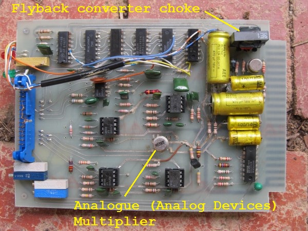
The flyback converter was to provide a minus rail for the multiplier. I think it might have run from plus and minus 12 volt supplies.
This board was found in a garage, and was covered with a thick layer of dirt and fluff. I only really wanted it to show here, so I washed it in the dish washer! Here is the rear view.
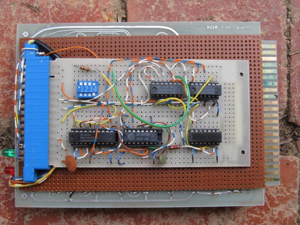
The small board attached to the rear is the shift register/ring counter MARK phase regenerator. As you can see this was built up as a “one off” prototype board. There never was a case made to “do this properly”.
In the case of this receiver, it worked without a hitch. We couldn’t do bit error rate tests because we didn’t detect any bit errors.
When looked at with modern tools, the scheme holds up well.
I have broken the simulation circuit up to make it fit on this page a little better.
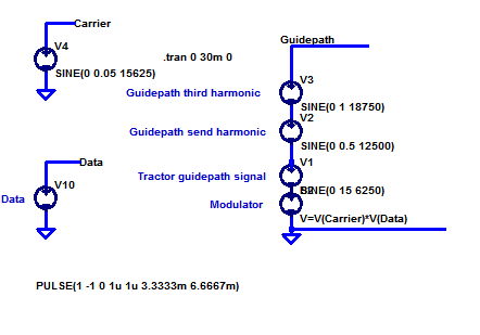
Here the signal on the guidepath is made up of the sum of The guidance signal of amplitude 15 volts, second harmonic of that at 0.5 volt, third harmonic at 1 volt (I am making it hard for the model, I don’t think the distortion of the guidance signal was really that bad!) and the modulated carrier with an amplitude of 50 mV.
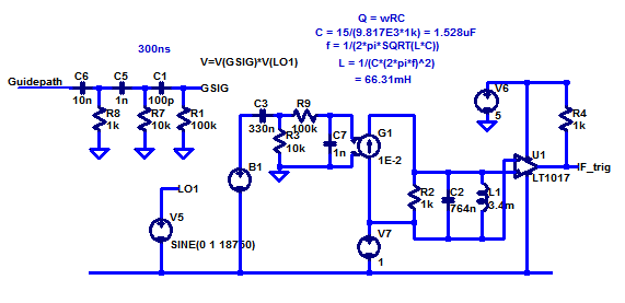
The initial filtering “front end filter” of three zeros provides a preliminary reduction in the guidance signal. The arbitrary voltage source B1 represents the analogue multiplier. The first local oscillator V5 is at the third harmonic frequency. The LC tuned circuit plays the role of the Riordan Gyrator. The LT1017 comparator is used as a trigger (RF people might say “limiter”)
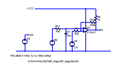
The arbitrary voltage generator B4 is set up as another multiplier, but it is only multiplying digital signals. It plays the role that was played by an EXCLUSIVE-OR gate in the real hardware.
Even 30 years later, I love the way the waveform of the data emerges in stages as we look at various points of the circuit. This was very exciting at the oscilloscope in 1978.

Top Left: The guidance signal is so large that the data is completely invisible on it. Top Right:. Even a passive filter of three zeros give a very different view. Middle left: After the multiplier. The data is at 3.125 kHz, the second harmonic of the guidance signal is at 6.25 kHz, the third harmonic is now DC and the Remnant guidepath signal is now at 12.5kHz. Middle Right: After the gyrator. The lowest frequency we see here is our signal. Bottom Left: the trigger picks the signal out (at IF frequency). Bottom Right: The red trace is the “raw” data. Notice that it is low for most of the time to the left of the trace, “mucky” in the middle” and high for most of the time to the right of the trace. The blue line is the “cleaned up” data.
The data was ISO1177 format (for a UART) at 300 bits per second.
Unfortunately, the driverless tractor system that this receiver played a part in was short lived. This was not a reflection on the driverless system but the fact that the warehouse workforce was not ready to share their work space with an automated system. This is why the “piggy back” board on the back of the receiver was never laid out as a printed circuit board. There were many interesting aspects to this project, but the thread that links it to my next story is in the title “Two and a Half Times”. It is very easy with a phase locked loop to generate two waveforms that are locked together with a non-integer relationship between the frequencies. In this case, the key was to place a carrier so it could be picked up with synchronous demodulation but which was remote from the harmonics of a large interfering signal. In the next case, the application for the number “Two and a Half” was quite different, but there were common threads as you shall see.
Hi Richard,
Seems like this was an enjoyable project to work on, especially for you as team leader. It’s a pity the system didn’t go into full service, but at least you demonstrated proof of concept. Looking forward to the next instalment. MJB
Richard… Can you make the font size for comments bigger?