Before I get down to the subject in hand, I need to draw your attention to a much improved power cable based hi-fi equipment enhancer. If the placebo effect (see comment from Nigel Machin to last post) works as he says, then this must be much more effective than the item I wrote about last time. Is there any limit to this?
http://www.tweekgeek.com/bybee-holographic-ac-adapter/
And now, for something completely different.
I recently had a little innocent fun reading blogs that I had been referred to by an employment agency. There was lots of interesting advice for the job applicant. There was not much advice offered for the applicant interviewer/selector. They are both difficult – being an applicant and being a person who must choose between the applicants.
I have done a bit of both over the years, and if I had not been taking the outcome so seriously, I would have found the process of observing the person across the desk from me very interesting. The interest arises from reflecting on the experience later.
There are many aspects of this that do not relate to the technical aspects of the job of being an electronics engineer. The psychology of both roles is interesting. The way both parties give so much more away then they realise is something that can only really be grasped much later, often when the experience of many of these encounters can be brought to bear. I reserve discussion of the non-engineering aspects for another forum, but there are some interesting points relating directly to the question of just what grasp of electronics the candidate has.
I have been the interviewer/selector more times than I have been the candidate, and will share some lines of questioning that I liked to use.
Here are two circuits that I have used many times over the years when interviewing candidates for junior engineer or technician positions. One of the reasons that I stuck with these circuits was that I discovered that after I had used them a number of times, I picked up patterns of response. Once I had calibrated these circuits, the candidates betrayed an awful lot about themselves very quickly. I had been reluctant to publish these in the past, because I did not want to encounter candidates who had swatted up on them. I think that that is unlikely now. Possibly these circuits are a little dated. Perhaps anyone wanting to use circuits such as these as test questions might want to change them a little to suit modern conditions. There is one analogue and one digital.
Analogue Circuit.
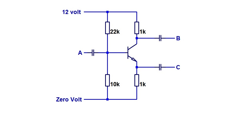
I didn’t come to the interview with this circuit printed out: I would sketch it in front of the candidate. Thus the candidate would have the time it takes to draw this freehand to take it in.
My first question would be “What is this?”
This is not the sort of question that has only one answer, but it is a question that gives the candidate plenty of scope to show how she understands what is shown.
I showed this to Ed Cherry when he was still at Monash. He told me that the Monash students did not study the “Concertina” circuit, as if that somehow made it a bit unfair to ask them about it. I reckon that what makes this circuit a really good interview question is that it gives the candidate who has never seen such a thing before a chance to show how she figures it out.
(Concertina circuit: http://www.r-type.org/articles/art-010p.htm. The circuit was also called the “cathodyne” in valve days http://www.valvewizard.co.uk/cathodyne.html.)
My next question would be, “What dc voltages would you expect to see on each of the terminals of the transistor?”
This immediately separated the sheep from the goats. I have had all sorts of weird responses to this question. I have even had a candidate attempting to work this out starting from the collector. I would often be asked about how accurate an answer I needed. I would say “Imagine that this had just been prototyped, and I asked you to check that the dc conditions seemed to be ok. You make measurements, but what do you expect? How do you judge if the measurements indicate a problem or not?
The next matter was small signal performance. I drew a small sine wave on voltage/time axes at the input, and two vacant sets of axes beside the outputs, and asked the candidate to show me what signals, to the same scale, I would expect to see on the outputs.
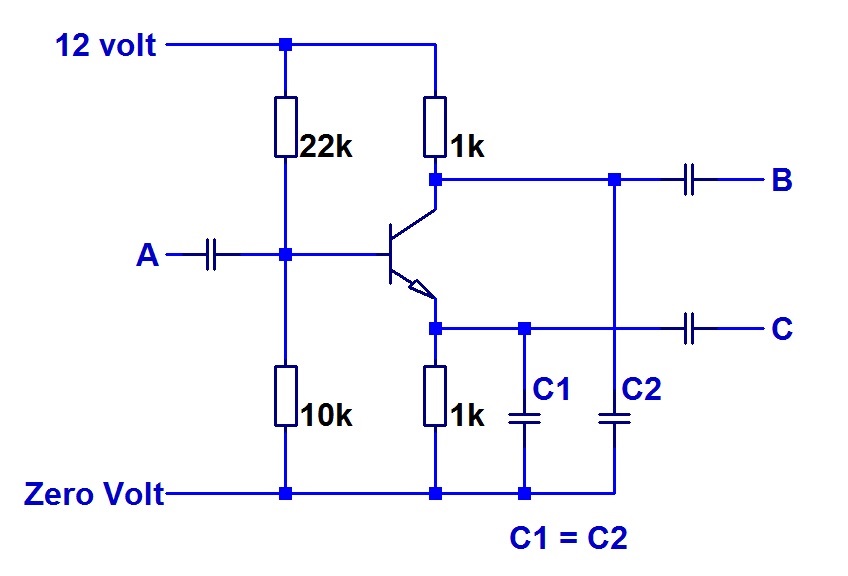
This is such a simple circuit, and yet at this point it had shown huge discriminating power amongst the hundred or so candidates that I have put it to over the years. For the candidate who seemed to be finding it easy sailing, I would propose some capacitative load on each output and ask for some indication on an asymptotic (straight line) bode plot of what effect this would have.
I’ll give you a hint that I did not give them. I would like to have seen bode plots representing emitter voltage, collector current and collector voltage in that order.
A Digital Circuit.
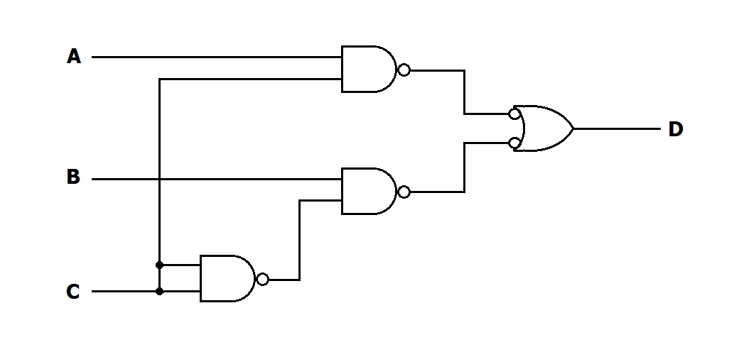
Then I would draw a digital circuit. This is what I would draw.
Some people were not familiar with the appearance of a logic symbol with an inversion bubble on the inputs. I always felt that this was a strange sort of naivety. Nevertheless, for those who had never seen such a symbol, here was a chance to think on their feet and show how they could figure it out. This circuit was drawn using a convention that used to be common of linking outputs with inversion bubbles with inputs with inversion bubbles whenever this is possible. This circuit also shows that this is not always possible.
My first question would be, “What is this?”
This time the initial question is one with a single correct one-word answer. To get this right straight away, rated the candidate highly. For everyone else, I would ask, “How would you describe the signal D in terms of the signals A, B, and C?”
Perhaps in the case where the candidate was struggling, I would ask “Can you tell me what
DeMorgan’s Theorem states?”
( http://www.allaboutcircuits.com/vol_4/chpt_7/8.html )
It always impressed me how much I could learn about a candidate with these two very simple circuits.
I was discussing these with my friend James Fenech, and he mentioned the alternative idea of giving the candidate a prepared test. That can be a good idea too. I have only sat a set test for a job application once. It was a cleverly contrived test with some tricky traps. I fell into a couple of them. James suggested that one could start with line of thinking such as my really simple analogue circuit (above) and set a task such as “Design a one transistor amplifier with a gain of three”. This reminded me of an article that was written in Wireless World by M.G. Scroggie who used to use the nom de plume “Cathode Ray”. He discussed a lifetime of interviewing young engineers and observed how the candidates had changed over the years. He had a pet question about the gain of an op amp. I don’t think that it was supposed to be a trick question, but it turned out to be a bit tricky for the modern candidate.
Was James’ question a “trick” question? To try to clarify this, I asked him for a more detailed specification. He replied:
“If I were setting such a question:
– 9V supply rail.
– 5k drive impedance to drive YOUR amplifier.
– 22k load impedance driven from YOUR amplifier.
– 20-20kHz operation.
– gain of 3.
– AC coupling required.
– Output voltage of 1Vp-p.
– 1 transistor only.”
“This is reasonably easy,” he wrote, “but requires getting a lot of things in line.”
I still couldn’t decide whether this is a trick question or not. I had a crack at it. With one interpretation of the requirement, I found that it was only just possible. maybe this is what James meant when he wrote “… requires getting a lot of things in line.”
Hmmmmmm.


