Posted 25-03-2016
HYTECO DRIVERLESS TRACTOR SYSTEM MODEMS

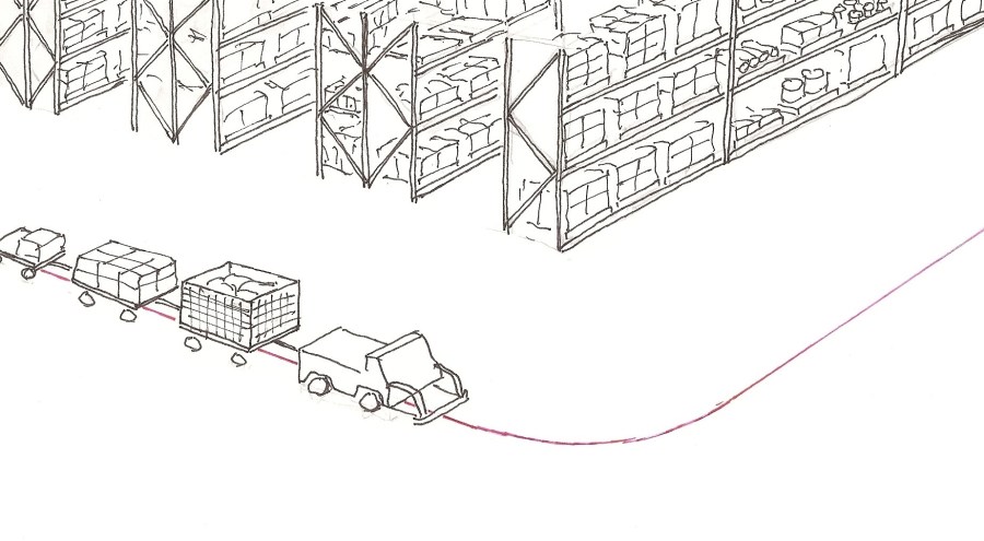
The Hyteco Driverless Tractor System was a scheme for running towing tractors around a circuit in a large warehouse. The tractors followed a guidepath which consisted of a wire set in the concrete floor. The wire carried a direct current with a 6.25 kHz sinusoid superimposed. The wire also carried other signals for communication purposes. The guidance system was an adaptation of a proprietary system that Hyteco had the agency for. Indeed, part of the justification for the development of the system was to sell more guidance equipment. The system had many interesting aspects to it. One of these was the provision for communications between the tractors and the central controller. Each tractor and the Controller had a central processor which consisted of a Motorola “D2Kit” which used a 6800 processor. This was 1978.
We had a “DECwriter” Printer/keyboard terminal which had a fixed speed serial port at 300 bits per second. I made a decision very early in the project that the system communications would all be ISO1177 style (UART Compatible – Start/Stop serial) so that the DECwriter could be used for sending or receiving test messages. Indeed I remember at one time a tractor with the DecWriter mounted on it was charging up the factory with a bevy of blokes running along behind feeding out the extension cord which was powering the DECwriter which was printing out “The Quick Brown Fox Jumps over the Lazy Dog” or something like that.
We had communication from the Controller to the tractor in a realistic environment, and we could prove it!
The decision to format the data stream in this way thus had an advantage (for exercising, proving and testing), but it also caused us some problems. In some places in the system, we had to derive a bit clock from the guidance signal, and that was possible, but in the technology of the day, it took quite a number of CMOS SSI integrated circuits.
ISO 1177 data is not always a good choice where signal to noise (and consequently non-zero bit error rates) is an issue. A UART only has to mis-read one START BIT, and probably the whole of the rest of the message is lost. Nevertheless, this was an early decision (as it had to be) and we were stuck with it and we stuck to it.
There were four distinct communications paths in this system.
1. Location Loops
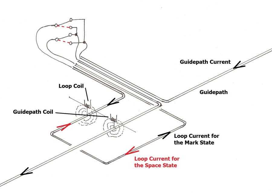
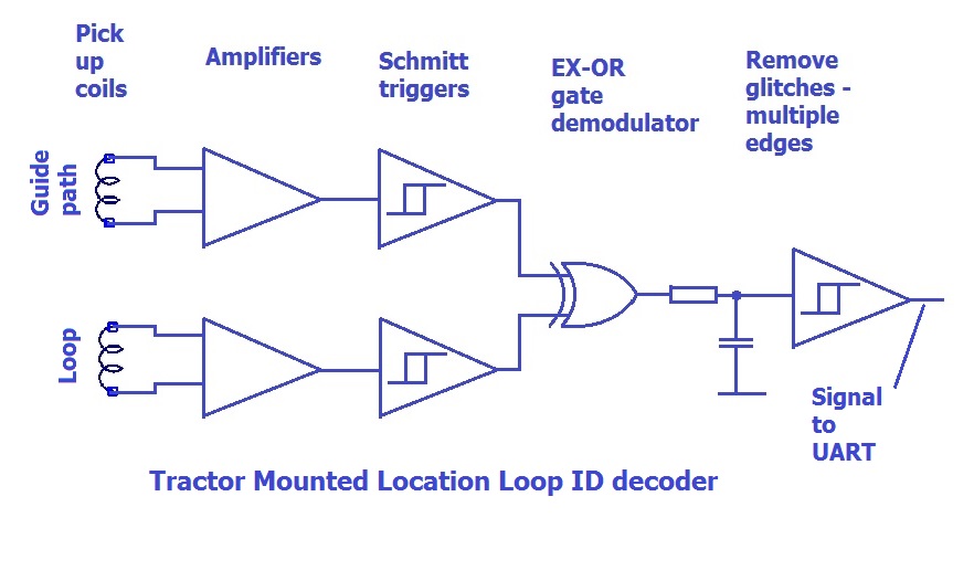
One was communication to tractors from particular places so that the tractor had location information. This might have been seen as a design challenge, but it was one of those things that worked first time and never gave any trouble. The scheme was to provide an auxiliary guide path signal which was phase-reverse keyed. the demodulator required no more than a schmitt trigger on the guidepath signal and the auxiliary signal, an exclusive OR gate and a low pass filter. Maybe there was a third schmitt trigger at the end, but the result was a channel that was trouble free when fed directly to a UART.
 Location Loop – set in the concrete floor, and connected to a box attached to a nearby wall. The box contains electronics that imposes a data byte on the loop by reversing the current in the loop. The two coils shown are mounted on a passing tractor.
 Block Diagram of Tractor mounted Location Loop decoder. Unequal delay in the Guidepath and Loop sensing circuits can lead to glitches and multiple edges on a change of logic state. the duration of these is very short compared to a bit period, enabling the very simple RC and trigger clean-up circuit to be used.
2. Turnouts
There were small circuit boards in lineside boxes that switched the guidepath current from one wire to another, and thus provided the function of a “turnout” or “pair of points”. The receive end of the communication to these from the central control was designed by a bloke named Peter Resmer, who made a good job of it. Like the location loop circuit, it was one of the aspects of the project that fell into place quickly and didn’t need constant revisiting.
Each of the other two communication paths was much more troublesome. These were Communication from the Central controller to the Tractors, which we called the “Down” direction, and communication from the tractor to the central controller which we called “Up” traffic. (One needs terms, and we chose these from railway practice. Our system was a railway system in every respect but one: it didn’t have rails.)
3. The Down Channel Communication from the Central controller to the Tractors
This was tackled first. There were several factors at play in determining the choices here. We were a bunch of young, inexperienced engineers and technicians. We were supposed to be designing a practical system: not making world shattering advances in the technology of the components. Any established designs that could be brought into play with minimum mucking around looked good. This was the early days of telephone line modems. Frequency shift keying was very popular, and there were many ICs available. Most of the data sheets had beaut looking circuits in the applications section. I was a bit naive about how reliable application notes circuits are in those days. We decided to use frequency shift keying an adapt a data book application circuit to suit our need.
The story of how we encountered problems and learned a lot and got this to work is a story in itself. We got it to work, but there had been troubles, and I didn’t want to launch into another troublesome task. Added to this was the fact that for the Down Channel, we could transmit a strong signal. The signal was added to the guidepath signal, and the only upper limit to the data signal power was the power at which it interfered with the guidance system.
In this respect, the Up signal path was completely different. The tractor ran on a concrete floor with the guidepath wire set in it. It was required that the tractor had about 100 mm clearance, so however the tractor was to convey the signal into the wire, it was most unlikely to be a high powered signal when established in the wire.
Whenever a communication system is asymmetrical in that one station communicates with the others, but that they don’t communicate with each other, then the optimum focus for investment is also asymmetrical. A broadcast transmitter working with a large number of receivers is the classic case. If improvements to the system can be applied at the transmitter, then they have to be applied only once. The result is that we have large powerful expensive broadcast transmitters, and large numbers of cheap, possibly not very sensitive or selective receivers. The same asymmetry rule applies whatever the direction of the traffic. The equipment in a cellular mobile phone base station will be vastly more expensive than any individual phone, but might not be vastly more expansive than the population of phones that it serves. There were no mobile phones in 1978, but this point was clear: The central controller circuit could be complex, but the tractor circuit should be simple and cheap.
The tractor transmit antenna was designed by Roger Riordan. I have described this in this blog before (“Time Passes 1” posted in August 2013. You can find it easily by placing “Riordan” in the search box.). It happens that that transmit antenna design does not have the bandwidth to carry the FSK type of signal used for the Up traffic.
I had been concerned about bandwidth for a completely different reason. The receiver had to pick out a small signal from a channel with other large signals on it. One aspect of our efforts to find the signal in amongst all the noise was to place the signal in a quiet place in the frequency spectrum, and use no more bandwidth than necessary. The FSK encoding used for the Down traffic had to use much more bandwidth than the theoretical minimum, as the characteristic relationship between frequency and voltage at the phase locked loop chip VCOs, and the need for voltage swing dictated a large difference between the frequencies representing mark and Space. A different scheme was called for.
When the signal is weak, and of narrow band, it become important to synchronize the transmitter and the receiver. The scheme chosen was to use frequency sythesizers clocked from the guidepath signal at the Tractor and at the receiver and place a phase modulated carrier at 2.5 times the guidepath frequency. The choice of two and a half times seemed to maximize the frequency difference between the signal and the guidepath harmonics. There were other advantages as well, which I will go into next time.

Interesting. All in 1978 – ish…
“Interesting. All in 1978 – ish…” — Is that the whole of Hugh’s comment? If not I can’t view the rest of it.