The story so far…
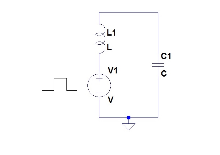
I have postulated that for high efficiency, one needs to drive a tank circuit in one of two ways: with a current drive,
or with a voltage drive:
It had not escaped my notice that traditional Class C stages did neither of these. Since posting those musings, information has come my way about how real Class C stages really did it, and I will pass that information on in a later post. For now, I continue to use the second of these.
I have investigated the introduction of amplitude modulation by pulse width modulation. Unfortunately, there is not a linear relationship between pulse width and amplitude of the ringing of the tank circuit, and I have introduced two schemes to overcome this non linearity. The first was negative feedback around the modulator and a following demodulator. Modelling showed that this could, in principle, give good results. I have since been informed that negative feedback around an amplitude modulated transmitter is a trick that has been used in practice.
The second scheme was a pulse width modulator that did not give pulse width proportional to instantaneous baseband voltage, but contrived a pulse width that would give the desired amplitude at the tank circuit. This gave good results as well.
I can see no reason why if a really high fidelity amplitude modulator was required then both of these techniques could not be used.
However a third technique has arisen. It is simpler than the other two. Maybe it could stand on its own in a low fidelity speech band modulator, or in combination with feedback around a demodulator for a higher fidelity application.
In developing the explanation of this third technique, I will not follow the path that led to its accidental discovery. However, by way of confession, I will tell you about the discovery.
When I was spice modelling the feedback around the modulator – demodulator combination, I was troubled by a crazy wobble that arose in the waveforms. For a while I thought that I had discovered a circuit instability that was being exposed by the LTspice, and I explored a few ways to deal with it. Soon it became evident that it was an artifact of the LTspice itself, and was completely cured by reducing the Maximum Step Time. I had learned a valuable lesson about setting up spice parameters, but more than that, I discovered that one of my attempts to quell the instability had revealed itself as a really valuable trick.
This “design by serendipity” is an interesting phenomenon: not to be dismissed as one of the paths to good design ideas. This is a discussion for another time.
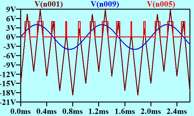
My initial pulse width modulator scheme was very simple. The carrier was generated as a triangle waveform. This was added to the baseband signal, and the sum offered to a threshold detector. The instantaneous value of the baseband determined how far up the triangle the threshold detector threshold was, and thus the width of the pulse.
In Post number 35, I reduced the carrier to 5 kHz so that it and a 1 kHz sinusoidal baseband signal could both be clearly seen on the same axes, and presented a graph to explain this modulator action.
I reproduce it here.
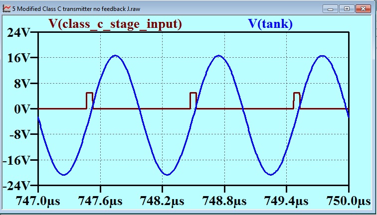
The next important detail in the explanation of this scheme, is the time or phase relationship between the excitation pulse and the voltage waveform at the tank circuit. I had shown this relationship in Post 37, and I reproduce that here as well:
The voltage on the tank circuit lags the fundamental component of the pulse waveform by 90 degrees.
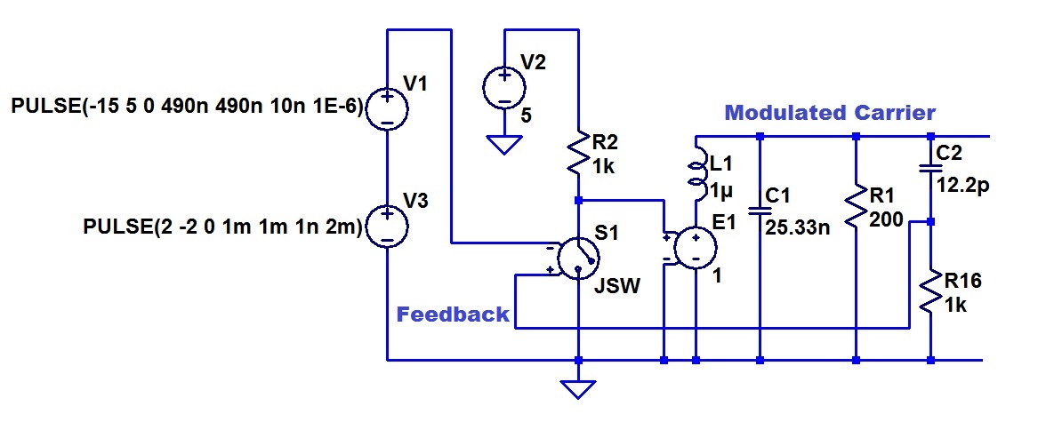
If we place an RC circuit with a break frequency that is much lower then the carrier, on the Tank, that will give a further ninety degrees lag. Overall, 180 degrees lag, or a suitable signal for negative feedback. Alternatively (and this is what I have done below) we can set up the RC to give about 90 degrees lead, which gives us an output that is in phase with the excitation, and then subtract this from the modulated carrier. Here is my circuit model:
The tank circuit is made up of L1 and C1. The resistor R1 represents the load (antenna if this is a transmitter). C2 and R16 are my lead network. They provide a feedback sinusoid at the carrier frequency and in phase with the excitation.
V1 is the carrier generator, which is of a triangle waveform at 1 MHz.
V3 is the baseband signal. In this case, it is a triangle waveform as well. I had developed the habit of doing this, as it is very easy to visualize the distortion if there is any curvature of the reproduction of the ramps in a triangle base band signal. I will quickly go through the way my model represents a pulse width modulated drive for the tank circuit. A comparator is represented by the switch model, which is closed for positive voltage on the differential inputs and open otherwise. V2 and R2 convert the switch state to a voltage waveform, and this is presented to the tank circuit by the voltage controlled voltage source E1 (which represents the power stage). As before, the pulse width modulation is executed by just adding the baseband to the sawtooth carrier. The switch/comparator converts this to a pulse width modulated signal as the base band shifts the carrier sawtooth up and down and varies the time during which it presents a positive value to the switch/comparator.
It will be seen that the switch is closed by a positive voltage, but that closed switch gives the negative state to the output drive. Thus the switch – voltage follower combination is inverting to the carrier signal. The feedback from the lead network is fed to the plus input to the switch differential input is thus negative feedback.
This circuit is the same as in previous postings except for the lead network and the application of this negative feedback to the modulator.
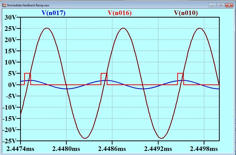
Here are the revealing traces.
The red trace is the output from the power stage (voltage controlled voltage source).
The brown trace is the voltage on the tank circuit (output of the transmitter).
The blue trace is the feedback signal derived from the lead network.
It can be seen that as the base band signal applies a bias to the triangle carrier to provide a wider part of the triangle to the switch, and to broaden the pulse, the feedback will apply an opposite bias and tend to make the pulse narrower – that is reduce the drive to the tank.
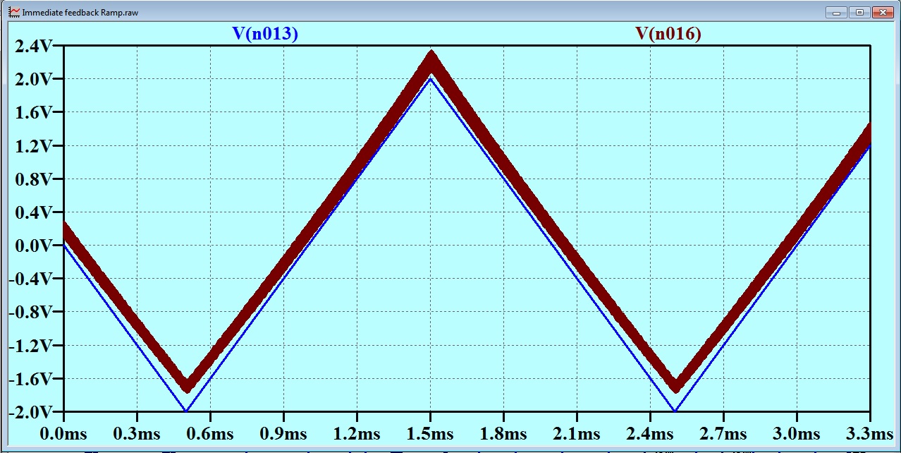
The result is shown below. The blue trace is the base band signal. The brown is the output from a synchronous demodulator. The thickness of the brown line represents carrier feed through. Notice that the brown line is “thicker” when the voltage is high: that is when the carrier amplitude is highest.
There IS some distortion visible. The brown line is seen to be slightly curved when shown in close proximity to the baseband signal. Note that I have used the circuit exactly as it was when I was trying to eliminate what I thought at the time to be an instability. I have not explored how much negative feedback can be applied here. When you consider that this negative feedback has been applied at a total cost of one capacitor and one resistor, it is seen to be a cost-effective result. It would most probably be worth incorporating in conjunction with overall feedback around a demodulator. I will leave this as an exercise for the interested reader.
This “Class C” business has gone on for longer than I had originally planned – and it is still yielding interesting material. I will leave it for a while now, and come back to it later.


