37 Class C Part 4 Focussed Modulator Design

The story so far:

After proposing pulse width modulation of the input signal of a Class C stage to determine the amplitude on the output, I showed that if we used a simple pulse width modulator that varied the pulse width in proportion to the instantaneous value of the baseband signal voltage, we got a distorted result.

I postulated two approaches to fixing this in Post 35. The first was negative feedback and the second was “smarter modulator”. I showed how effective feedback can be in Post 36. Now we turn to the “smarter modulator”.

The short version is that the output (in real life – high powered) tank circuit is mimiced with a low voltage LC circuit. This circuit is fed with a variable width pulse to maintain the amplitude close to that of a reference signal obtained by amplitude modulating a representation of the carrier with an analogue multiplier.

I will provide particulars and then show the result.

Particulars

There are two steps.

First, the carrier signal is processed to generate various special signals that are required by the modulator proper.

It will be easier to find what follows clear if it is remembered that the tank circuit has the property that the quasi sinusoidal on it is placed so that the driving pulse falls on the positive going zero crossing.

1 Tank waveform

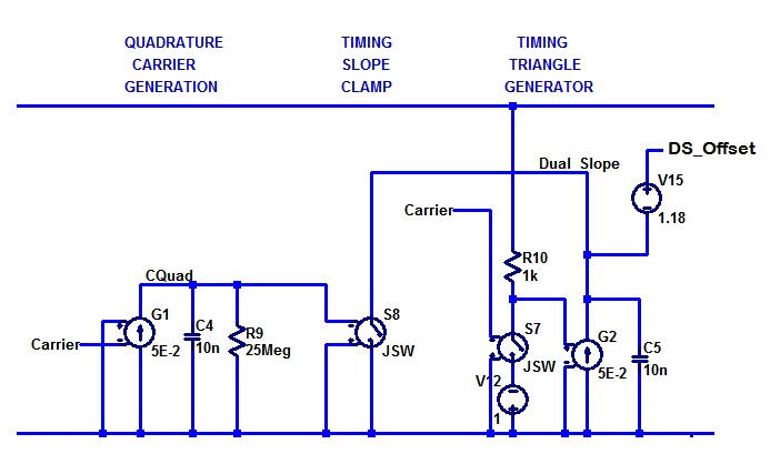
The first signal generated is a signal I call “dual_slope”.

The signal has a notch shape that is centred on the positive going zero crossing of the carrier.

2 Dual_Slope

This could be generated in any number of ways. If you are interested, this is how I did it.

3 Timing triangle generator

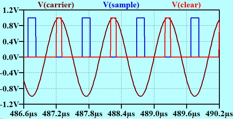
The second is a pulse “Sample” that occurs during the time when the carrier is near the most negative value. This pulse is accurately centred on the time when the carrier is at exactly the minimum value. See the blue trace below. The third is a pulse of less critical timing “Clear” that occurs later.

4 Sample and Clear

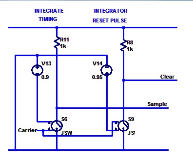
As before, I won’t go into the details of how these pulses are generated, but will show my model schematic for those interested.

5 Sample and Clear generation

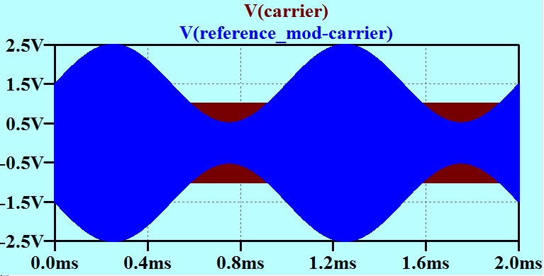
The only other signal required for the modulator is a representation of the amplitude modulated signal that the Class C stage is to produce. Of course in this low level signal modulator board, this is easy to do with an analogue multiplier IC.

6 Analogue multiplier modulated carrier

Second Step
Now we come to the actual Pulse Width Modulator for Low distortion Class C stage.

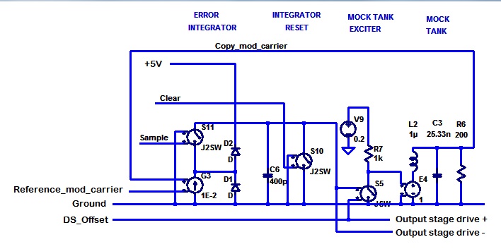
7 Modulator

It is easiest to describe the operation of this when it is already running. It is easy enough to extend this to graceful start-up. I will leave that to the imagination of the reader.

To the right of the circuit diagram there is a tank circuit and an exciter arranged just as I have arranged these in previous Class C stage models. The idea here is that these are all small signal components on the “modulator board”. It has appeared later that there might not be any reason for this “Mock Tank Exciter” and “Mock Tank”, as the actual exciter and tank could play the role here. I will leave this as it is for this explanation.

The voltage on the Mock Tank is compared with the modulated signal from the analogue multiplier at the voltage controlled current source G3. This then provides a current that is proportional to the difference. This current is shunted away by diode D1 or diode D2 except when the voltage controlled switch S11 is closed during the “Sample” time.

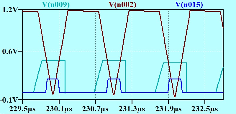
8 Modulator waveforms

The voltage on the Mock Tank circuit is the brown trace. The reference modulated carrier is the blue trace. It will be seen that the magnitude of the reference modulated carrier is greater at the negative excursion. During the Sample time (red trace) the current representing the difference is used to charge capacitor C6. At the end of the Sample pulse, the charge on C6 represents how much the Mock Tank circuit is falling behind the reference signal. This is then used to determine the duration of the pulse of energy imposed on the tank by the exciter in the following cycle. C6 is discharged on the Clear pulse (not shown) The voltage on C6 is converted to a width of a pulse that is properly centred so as not to introduce phase modulation by comparing it with the dual_slope signal.

9 Pulse width modulation

Here the DS_Offset (Which is “dual_slope” with an offset added) is shown in brown. The voltage on the capacitor C6 is green as before. The blue trace shows the excitation signal for the Mock Tank. It is high whenever the C6 voltage is higher than the voltage of “dual slope”. It can be seen that this scheme will provide a variable pulse width to excite the tank, and that the width will vary as required to provide just enough energy to the Mock tank to have its voltage fall just a little behind that of the reference signal. At the same time, the driving pulse is properly timed so that there will be no phase variation as the amplitude is modulated.

I am writing this up many weeks after I developed the model. There are various reasons for regarding this as unnecessarily complicated. The complication would all be accounted for in a very small board area of small signal circuitry, so would be readily born if it gave the best result. What result does it give?

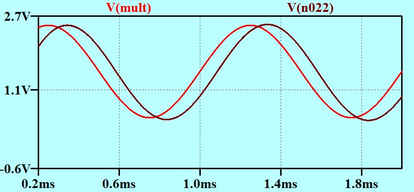
10 input vs demod

The red trace is the base band signal at the very input to the model.

The brown trace is (with attenuation and offset) the output of a synchronous demodulator on the high powered tank circuit.

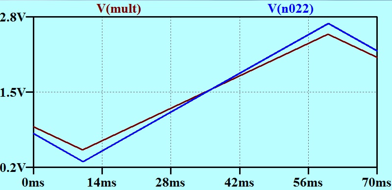
One way to check for linearity is to modulate with a slow ramp and look for the straightness of the ramp on the output. here is what we get.

11_sawtooth that is better

The brown trace is the input to the modulator, and the blue trace is an attenuated version of the output from the demodulator. That is linear!

Compare this with my initial “crude” pulse width modulator in which the pulse width is proportional to the voltage.

12

36 Class C Part 3

36 Class C Part 3 Feedback around Modulator

The story so far:

I have investigated the idea of a “Class C” amplifier and pushed the notion that the feature that the active device conducts for less than half the cycle is not definitive. It seems much more important to dwell on the high efficiency amplification without regard to distortion, and then recovery of the wave shape afterwards. In AM or CW transmitter service, the recovery is carried out by a high Q tuned circuit called the “Tank Circuit.”

Although possibly not available to “old time” circuit designers, the idea that a high efficiency active device that is working as a switch, could be modulated with pulse width modulation seems attractive. Unfortunately a very simple modulator that gives pulse width proportional to signal gives a distorted amplitude modulation envelope.

Here is the waveform that I obtained when I modelled a circuit consisting of these stages:

1. Pulse width modulator
2. Switching Power Stage
3. Tank Circuit
4. Diode demodulator.
Pulse width modulated sine simple waveform

The brown trace is the modulating waveform, and the blue trace is the output from the demodulator. Note that the blue trace is much “broader” on the positive excursions than on the negative ones.

See my Post “35 Class C part 2”.

It was evident that the simple law chosen for the modulator was not right for the characteristic of the tank circuit in changing pulse width back into sine wave amplitude. I suggested two remedies. The first, was to put negative feedback around the whole modulator – power amplifier – demodulator system: the second was to design a pulse width modulator that varied the pulse in a way that would give the correct result at the Tank Circuit.

Today’s post is to explore the first: Negative Feedback.

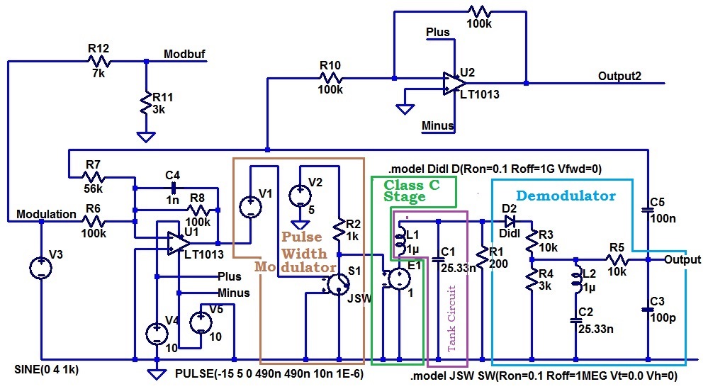
Here is my model circuit:

Feedback diode circuit

The demodulator is the diode demodulator we saw in the last post. I mentioned then that I added L2 in series with C2 to make a trap as I wanted to reduce the carrier, but did not want to put filter poles where they would interfere with my feedback loop. Notice the resistive divider R3, R4. This reduces the asymmetry that one gets if a shunt capacitor is placed directly on the cathode of the diode. In such a case, the diode charges the capacitor quickly, but it will discharge much more slowly. In this circuit, C3 and C2 are charged and discharged with much more similar resistances.

That’s the logic of it anyway. Probably completely invalidated with the addition of the series LC trap. Maybe diode demodulators is a subject for another day.

The resistive divider on the Modulation signal giving the signal Modbuf is just there so that we can see an input signal and an output signal that are similarly scaled.

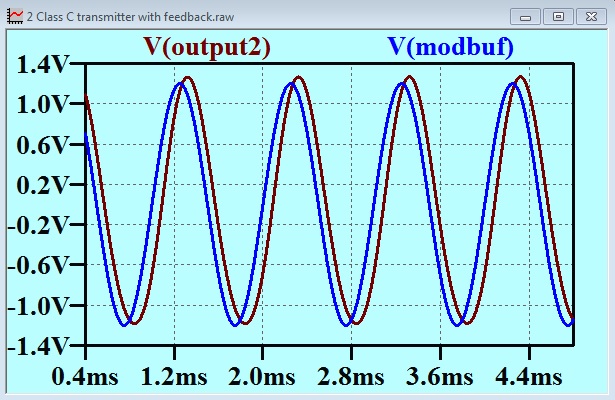
Here are the traces.

Feedback diode modulator traces

It is easy to see that the output signal is very much less distorted than without the feedback. As the output waveform is not created with a continuous process (the pulse width modulation), I cannot simply run a spice FFT on the output to measure.

I calculated the phase shift of the base band signal as it found its way along the forward path. The actual amplitude modulation of the carrier at the tank circuit is lagging the modulating signal by about 2.2 degrees. The output of the demodulator is lagging the modulating signal by 30 degrees.

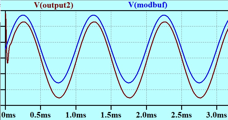
I tried substituting a synchronous peak detector for the diode detector. This effectively gave me a sample and hold on the peaks of the full wave rectified modulated waveform. This gave me a minimum ripple and enabled me to reduce the low pass filtering required for a smooth baseband signal. The result is shown below. You will see that the brown trace (output of demodulator) lags behind the blue trace (modulating signal) very much less with the synchronous demodulator.

sync demod

35 Class C Part 2

In “Class C part 1”, I wrote about a discussion I had had with the designer of a low powered AM broadcast transmitter. That was Brian Cabina, who I had met through the Music Broadcasting Society. Must have been in the early 1970s. By the time that society began transmitting, the FM band had become available, but during early planning, it was proposed to utilize the AM band. New frequency allocations were being opened up (One was taken up by 3CR, for instance), and it had been hoped to grab one of these.

He had told me that with an amplitude modulated Class C transmitter, one had to put the modulator on the output of the last stage “because with Class C there is too much distortion”.

AM Transmitter with modulation of the power to the Class C output stage
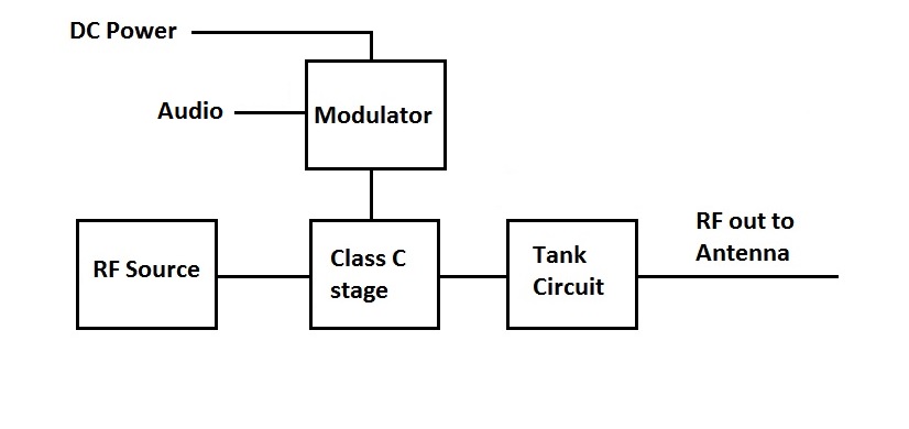
AM Transmitter - High Power Modulator

There is a heavy price to pay, as a portion of the power for the RF power amplifier has to be provided by an audio amplifier. This was expensive power, both in terms of capital cost, and in terms of efficiency.

I suggested that the blanket statement “with Class C there is too much distortion” is nonsense, and asked the rhetorical question “Can I justify that”?

My justification is that there are two completely independent avenues for distortion in a Class C transmitter and to blur the distinction between them, by grouping them under the heading “the distortion” is to prevent precise discussion.

Here are the two distinct distortions defined in a way that in my mind are clearly distinct.

Distortion 1.
This is distortion of the RF carrier in the Class C amplifying device. This distortion is removed (more or less) by the filter on the output. In traditional AM transmitter (or CW transmitter, for that matter) practice, the filter takes (took) the form of an L-C tuned circuit called the “Tank Circuit”.

Distortion 2.
This is the distortion that would be introduced in the audio channel between the input to a small-signal modulator on the input to the Class C stage, and the audio channel as it appears in the form of amplitude modulation on the output.

Distortion 1 is generally gross distortion indeed, and if that magnitude of distortion were to appear as Distortion 2, then that would certainly disqualify the circuit for serious AM work. However, Distortion 2 is either not related at all to Distortion 1, or related so loosely, that we can address Distortion 2 without regard to Distortion 1 at all.

If we were to modulate the signal at the input to a Class C stage, so as to achieve linear amplitude modulation of the output carrier, then what form should that modulation take? Not amplitude modulation. The Class C stage earns its stripes for efficiency by behaving as much like a switch as possible. The active device is either “on” and exhibiting as low a resistance as possible, or it is “off” and (in the instant) looking like an open circuit at the output. An exception that is possible, but divergent from traditional practice is that either one output device is “on” or another is, so between them a low resistance is presented to the output at all times. (See “Tuned Circuit with Voltage Drive” in the last Post “34 Class C Part 1.)

This is much more obvious to us these days now that we are familiar with switched mode power supplies, than it was to many armchair philosophers who contemplated Class C circuits in years past.
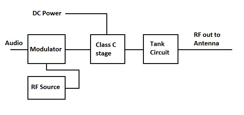
AM Transmitter - Low level Modulation

AM Transmitter with Low level modulator that modulates the signal to the Class C Stage

Our driver circuit modulator must maintain the signal amplitude to maintain the output stage efficiency. This leaves only one choice, the modulator must be a pulse width modulator.

This raises two questions.

Question 1.
If our transmitter block diagram has a small signal pulse width modulator followed by a Class C stage, is it possible in principle to provide an overall low distortion path to the audio.

Question 2.
What are the implications for the Class C stage of driving it with a signal of varying pulse width?

Let us go back a bit…
The tuned Circuit with voltage drive that I suggested in the last post was not really practical in “valve days” as the tuned circuit circulating current all passes through an active device. Any tuned circuit that was pitched at such a high impedance that the on resistance of a valve would not impose too much damping, would have much too much voltage swing for the valve to survive.

The huge differences between the old and new technologies are so obvious, that we don’t often bother to put numbers to them. Let us do just that in this case.

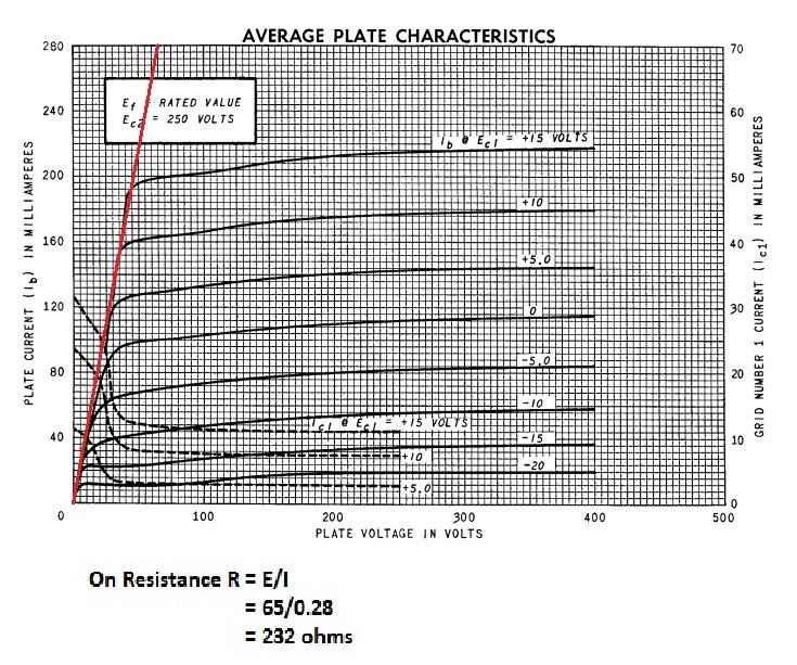
A 6V6 beam Power tetrode has a peak anode volts rating of 1200 volts, and a maximum anode current of 105 mA . The data sheets did not cite an equivalent of “RDSon”, but I estimated this graphically in the last post as 232 ohms.

An IXTP3N120 N channel MOSFET available at the one off price of AUS$13.461 from Element 14 has a maximum drain current of 3A and an RDSon of 4.5ohm. To get this low on resistance with 6V6s, we would have to have 52 of them in parallel. The change from one technology to another has not just made a change of degree in some parameters, it has of course made a change that has made completely new circuit arrangements available to us. This is blindingly obvious when we think about circuits such as switched mode power supplies, but it applies to Class C,   RF power amplifiers as well.

These days we might search in a particular area of our “concept space” for a high efficiency design, and find a good result. That very same area was disqualified in the “valve days” on the grounds of heater dissipation alone. (The heaters in 52 6V6s dissipate 147 watts) In the real world 21stcentury, we might choose a different voltage range (lower), a different current range (higher) and a different value for “on” resistance of the active device(s). We choose these on their merits, rather then matching the performance of a huge number of 6V6s in parallel.

A Class C stage, which you might remember, is characterized by me (if not by the rest of the world) as one in which the (an) active device “is driven so as to provide a switching type of waveform without regard to distortion, and then the signal is recovered from the harmonics by a high Q tuned circuit called the Tank Circuit.”. Such a stage can be built around what I called the “Tuned Circuit with Voltage Drive” in the last post. Here is the model circuit again as a reminder.
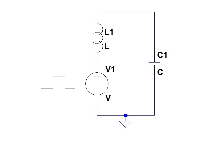
Tuned Circuit with Voltage drive

In this (what an old colleague of mine would call a) circuit topology, the circulating current in the tank circuit all passes through the active device(s) in the voltage source. Internal resistance in the active device(s) will be in series with the L and C. This is only practical if the internal resistances are very low. This is the case with (for example) MOSFETs with a circuit like that in a switched mode “half bridge”.
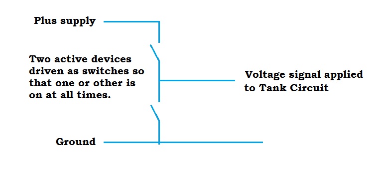
Model of Voltage source for Tuned Circuit with Voltage drive

Here is an amplifying stage put together along these lines.

Tuned Circuit with Voltage drive hoo

We start off with a source of signal at the carrier frequency. This is squared up with a trigger (which the RF boys (and girls) would call a limiter(?)) which I have implemented with a spice switch element. This converts the signal into a train of pulses which drive a complementary pair

The spice switch model has an “On Resistance” parameter, which I have set to 0.1 ohm. This accounts for the distorted nature of the waveform at the output of the power stage. This output has to carry the large sinusoidal current in the Tank Circuit.

The very output, the voltage imposed on the load resistor R1, is a sinusoid with low distortion, which we might regard as a recreation of the waveform on the input to the amplifier.

This “topology” which one might regard as an implementation of the “Tuned Circuit with Voltage Drive” ideal, will appear in several examples to follow.

MY definition of “Class C” includes the concept “ without regard to distortion”, and this is embodied here. The signal for exciting the Tank circuit becomes a train of pulses, and then is returned to a sinusoidal form by the Tank Circuit itself. Is this the distortion that I was warned about when I was a youngster? It is what I defined as Distortion 1. above?

What are the implications for Distortion 2 (the distortion of the modulating signal) of my practical implementation of “Tuned Circuit with Voltage Drive” topology?

Let us investigate this.

There are really only two ways we can apply modulation to the train of pulses at the output of the limiter. One is to modulate the amplitude of the pulses, and the other is to modulate the width of them. A moment’s thought will reveal that the modulation of the amplitude of them, amounts to the varying of the voltage source V1 in my circuit model above. This is the ordinary old modulation at the output of the RF amplifying stage, with the attendant disadvantage that some of the power to the output stage has had to come from an audio amplifier and is expensive power.

Pulse width Modulation of the Drive to a Class C Output Stage

Here is my first crack at a model to demonstrate this:

Pulse width modulated sine simple circuit

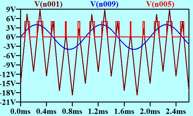
The pulse width modulator is set up to modulate the carrier with a 1 kHz sine wave. This is done very simply by adding the modulating sine wave to a triangle wave at carrier frequency and then passing the sum to a zero crossing detector. I have demonstrated this with the waveforms below in which I have reduced the carrier frequency to 5 kHz so that the carrier waveform and the modulating waveform can both be seen clearly on the same axes.
Demo waveforms

Here the blue line is the base band signal. The brown trace is the blue line with a triangle at the carrier frequency added to it. The triangle has the same slewing rate on the positive and negative going slopes. The red trace is the output of the zero crossing detector. This arrangement of pulse width modulator has pulses that are centred in a periodic fashion. That is the fundamental of the fourier series does not have phase jitter. This pulse width modulator has pulses with a width proportional to the voltage of the baseband signal. Is that the right characteristic in this case?

In this model, I have represented the power output active devices as a spice model voltage follower. You will understand that the circuit models that I present here have been placed in an order that has, I hope, a logical pattern to it. This is by no means the order in which the models were created. During the evolution of each model, there have been several steps that we will not bother with here. It just means that changes crop up from model to model. Generally, I won’t comment on these if they have no impact on the argument.

A simple diode demodulator is used. The introduction of L2 in series with what had been a low pass capacitor C2 to make it into a trap, had been done at some stage to reduce the carrier ripple on the output. I wanted a clean recovery of the baseband signal without placing a pole too low. This was my quick “no thinking” solution, which suited me in the moment better than a multi-pole filter.

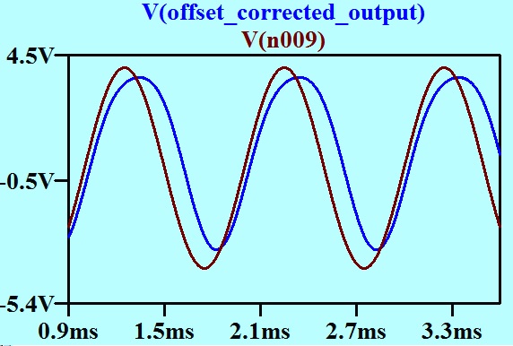
Here is the base band modulating signal and the output on the same axes.
Pulse width modulated sine simple waveform

The brown trace is the modulating signal, and the blue trace is the output of the demodulator. Considerable even-order distortion is evident. Is this the distortion that I was warned about all those years ago, that I have identified as Distortion 2?

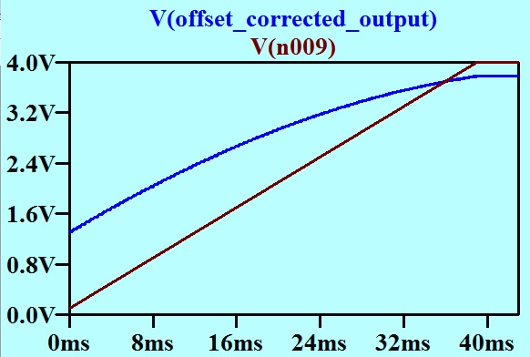
It can possibly be seen more clearly if the base band signal is replaced with a linear ramp.
Ramp

Here the modulating signal is a trapezoidal wave of low frequency. Here we look only at the rising edge (brown trace). The blue trace is the output of the demodulator.

If this is Distortion 2. then it seems pretty benign to me, and aught to be amenable to a little fixing with negative feedback.

Then again, and this is a possible second approach, maybe the “pulse width proportional to voltage” is not the correct transfer function for the pulse width modulator in this application. Maybe a modulator designed with a little more care would fix this distortion.

These two approaches – negative feedback, and smarter modulator – will be examined in the next post.

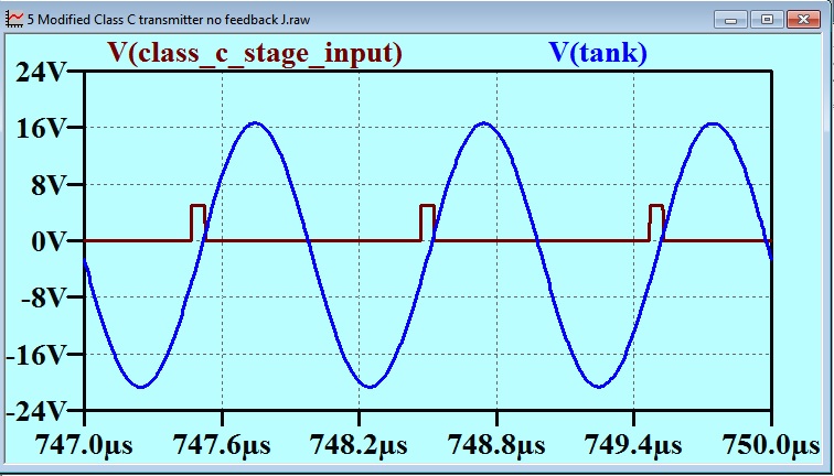
By the way, I am aware that conventional Class C circuits are not amenable to pulse width modulation. I suspect that the tank Circuit would have to be re-tuned every time the pulse width was changed.

Here is a “modern” (solid state) schematic for a Class C transmitter that I found on the internet.

1W_RF_Amplifier

Aren’t RF designers funny people! It seems that the active power device is also performing the role of limiter (approximation to zero crossing detector). I interpret the FD700 diode between base and emitter as being to provide a symmetrical non-linear load for C1 so that the transistor can be driven hard on positive excursions. Why don’t RF designers have to worry about transistor saturation? You can see that the reactance of the RFC is in with the Tank circuit when the transistor is “off”, but not when it is “on”. This circuit could not be used with pulse width modulation as the Tank Circuit tuning would be adversely affected.

34 Class C Part 1

Foreword

This post has been delayed, not through any problem getting the content together, but by problems presenting the content on the BLOG page. My good friend Andrew Beal has been helping me with those problems.  They are not all solved yet, but I am publishing this now (19-04-2015) as I am concerned that what is actually posted has fallen too far behind with thinking out material for this blog. As I attain more mastery over my formatting problems, I will come back and knock this post into better shape. And now, to the post…

Class C Part 1.

It used to be that much was made of the division of the bias arrangements for active devices into three classes. Class A, Class B and Class C. Some feature had to be found to easily distinguish these. The feature that was usually used was the proportion of a signal waveform for which the active device was conducting. This was expressed in degrees. Thus it was said that a Class A stage conducted for 360 degrees of the waveform, a Class B stage conducted for 180 degrees of the waveform, and a Class C stage conducted for less than 180 degrees of the waveform. In the case of vacuum tubes, there were many divisions between these. Thus we had push pull amplifiers classed as AB1, AB2 etc. It all depended on how one contrived to pass the amplifying task from one active device to the other at the zero crossing. These “intermediate classes” are explained in detail in The Radiotron Designers’ Handbook  Chapter 13 Sections 1 and 7 (1).

It has been shown by Douglas Self (2) that when junction transistors are used as the active devices, there is no advantage in attempting to find an optimum with a compromize between the classes, and it is best if a linear amplifier is required, to commit to either Class A or Class B. An optimum design of a Class B stage has such a small output device quiescent current that it doesn’t warrant any subscripts after the B.

I have never designed a Class B MOSFET amplifier, but I have been reliably informed by one who has, that there is a particular trick. MOSFETs do not suddenly snap from their linear operation value of gm to zero as they pinch off, but go through a gradual transition. In an amplifier with  a push pull complementary pair of Class B MOSFETs they are biased so that with zero signal, both output MOSFETs are sitting on their transition between linear operation and “off” so that each is exhibiting  a gm value of half that for linear operation. At this point, they are both conducting (a little) and contributing half of the combined gm each.

As I see it, the number of degrees of the sine wave cycle is not really a definitive measure. All we can say is that active devices are set up to take half the signal each: one takes the positive half waveforms, and the other the negative half waveforms. Class B amplifiers have an efficiency advantage, partly because they exploit very particular properties of an audio signal.

An audio signal:
(a) Hovers about zero and deviates from this in both polarities in a more or less symmetrical pattern.
(b) Has a wide dynamic range. This means that an amplifier that has to meet some particular maximum power requirement will spend a lot of time delivering much lower output power.

Class C.

This is traditionally defined as an amplifier design style in which the active device is conducting for less than 180 degrees of the waveform cycle. This class evolved in a very particular application: the power amplifier for a radio transmitter. This application also has some very restrictive features the key one being that the bandwidth of the signal is small compared with the centre frequency.

This means that the amplification stage can be designed with an eye to maximum efficiency and very little (or none at all)   effort to minimize distortion. The waveform distortion can then be reduced by a tuned circuit at the output. The tuned circuit that does this waveform restoration is called the “Tank Circuit”. I wonder how that term originated. (The expression “Tank Circuit” does not appear in my hard copy OED. It is to be found at http://www.merriam-webster.com/dictionary/tank%20circuit but without attribution.)
It seems that it is relatively easy to build a tuned circuit that has a high enough Q to make a practical approximation to a sine wave when being driven by a non-sinusoidal periodic waveform, and yet a low enough Q to accommodate the sidebands when amplitude modulation is applied. After all, the second harmonic of the carrier is usually a lot further away than the upper sideband.
There is even an opportunity to exploit the steeply falling spectrum of most audio material. This makes it possible to boost the high frequency end whilst making very little increase in the peak value of the composite waveform. This means that it would be possible to choose a Q for the tank circuit that is so high that the extremes of the sidebands are attenuated, but then compensate for this with pre-emphasis in the audio channel before the modulator. This would be a very minor step compared with the spectoral shaping, dynamic range reduction (compressing and limiting) and peak to RMS ratio reduction jiggery pokery that routinely goes on in AM transmitters.
It is always possible to add low pass filtering to further reduce the harmonics introduced in the Class C stage, and perhaps the “pi coupler” used for impedance matching, provides some low pass filtering at no extra cost.

Once freed of the requirement for linearity, and with a focus on high efficiency, we need an active device that acts like a switch. It is either a zero ohm conductor, or an open circuit, and it does not dally about wasting energy in some intermediate state. This sort of requirement is very familiar to us in these days of solid state devices and switched mode power supplies. It might have been obvious in the days of yore, but with thermionic devices, this was an ideal that must have seemed very remote.  Designers had to make do with what they had.

There are two complementary ways we can add energy to the tuned tank circuit without interfering with its tuning or severely lowering its Q. One is to introduce a periodic waveform voltage in series with the L and C, and the other is to introduce a periodic current waveform to the parallel tuned circuit.
Tuned Circuit with Voltage drive
Tuned Circuit with Voltage Drive

Tuned Circuit Current drive
Tuned Circuit with Current Drive

The scheme of driving the tuned circuit with a current is the scheme used in linear rf amplifiers in receivers, of course, where the high resistance of a pentode anode, collector or drain approximates the current source. The use of current drive is much more difficult in an environment where high efficiency is required. I have experimented (in simulation) with a circuit where a switched current is derived from an inductor. It came out as a circuit of a boost regulator, but with a tuned circuit instead of a reservoir capacitor on the output. Both switches have to be active switches (can’t use a diode for one of them as in a conventional boost stage), but the biggest problem is that the inductor that provides the current to the tank circuit, also detunes it. This could be corrected for, but only in a circuit where the duty cycle is fixed.

The one thing, we cannot do to provide energy to the Tank Circuit is to periodically connect it to a voltage source via a resistor. One would think that if the resistor value were low enough to transfer energy effectively into the tank circuit, then it would be low enough to lower the Q.

Yet, this is exactly what a traditional Class C output stage does.
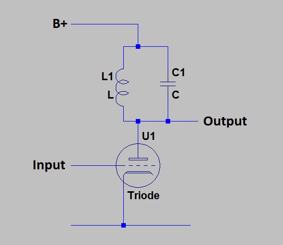
Triode in Class C
Triode in Class C

Sometimes a pentode is used, but the higher dynamic plate resistance is of no use here. When the valve is conducting, it is “hard on”. The high resistance available from the pentode when biased in the linear region is not available. One supposes that the lower Miller capacitance of the pentode might be a benefit. (And Possibly lower “On resistance” – see below.)

So the valve is used in a very unsuitable way, but possibly in the only way that was available given the characteristics of valves. When a valve is used as the active device, the characterizing feature of “conducting for less than 180 degrees of the waveform” arises. Here is a model circuit that I have used to investigate the effect of varying conduction angle.
Duty cycle model complete small

This is a bit much to take in as (unfortunately) my crude circuit drawing graphics capability makes for bad presentation of much data in the available width. I will quickly run through this model a section at a time.
Duty cycle model 1 signal generation
This very uninformative circuit segment will become clear when I explain it. V2 is a voltage generator that provides the 1 Megahertz signal as a triangle wave. V3 imposes a ramp. The combined effect is a triangle wave with a slowly increasing offset. To a following circuit that is sensitive only to whether the result is positive or negative, the result is a pulse train at 1 MHz that varies from zero to 50% duty cycle.
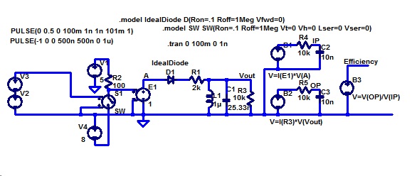
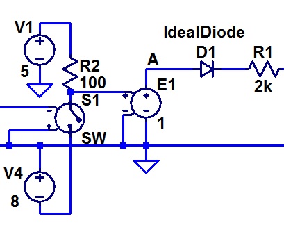
Duty Cycle model 2 supply and valveThis part represents the supply and the valve. The voltage controlled switch is set up to vary with the control voltage in such a way that it reproduces the pulse train as described above. The 100 ohm resistor R2 and the two supplies V1 and V4 turn this into a pulse train that is at 5 volts during what we are representing as the “on” time, and minus 8 volts otherwise. The minus 8 volt supply is not part of the valve modelling, but is required to make the rest of my model work. It stops the ideal diode D1 from conducting during the “off” time. R1 represents the valve “on” resistance. You will observe that none of the voltages or resistances in my model have realistic values. I worked on this model until it worked. I have not spent further time rescaling it.
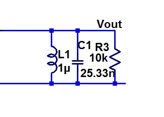
Duty cycle model 3 Tank CircuitHere is the Tank Circuit and the load.

The final part is that which measures the efficiency.
Duty cycle model 4 Measurement

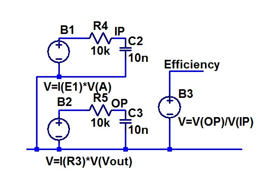
The arbitrary behavioural voltage source B1 has an output voltage that is the product of the valve current and voltage. It thus represents the instantaneous power being provided by the power supply of the transmitter. The resistor R4 and capacitor C2 give us a represtation of this averaged over several cycles.

Similarly B2 provides a voltage representing the product of the current and the voltage in the load. In other words instantaneous output power. R5 and C3 give us a represenation of this averaged over a few cycles.

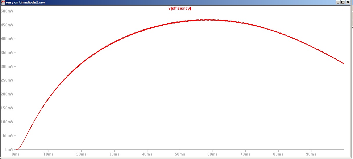
The third arbitrary behavioural voltage source, has an output voltage that is the ratio of output power over power supply power, or in other words, efficiency.
here is the result.
Class C Efficiency vs ontime diode and negative bias

We can see that the maximum efficiency (of about 47 percent in this case) occurs when the duty cycle is about that obtained 0.6 of the way through the run. That is 0.6 of 180 degrees or 108 degrees. There you have it: for maximum efficiency for a valve in Class C, we can turn it on for about 108 degrees of the carrier waveform cycle.

This is an outcome that agrees remarkably well with actual historic practice, given the crudeness of my model, but I do not regard it as definitive. I would define Class C this way:

A Class C amplifier is one suited to a narrow band fixed frequency signal. The valve is driven so as to provide a switching type of waveform without regard to distortion, and then the signal is recovered from the harmonics by a high Q tuned circuit called the Tank Circuit.

This is the 21st Century, and we are well into the solid state era. How does that affect this style of amplifier?

When I was a youngster, I spoke to a bloke who had built a low power AM Broadcast transmitter. It was for use on an island, and I believe the figure of 100 watts was mentioned. The Class C valve was an 807.

I asked him about the common practice (which he had followed) of placing the modulator on the very output of the transmitter. This is an expensive practice, as it requires two high powered amplifiers – a Class C RF amplifier and a (usually Class B push pull) audio amplifier.

“You have to place the modulator on the output because with Class C there is too much distortion” he said.

I contend that when simply put like this, this statement is nonsense. Can I justify that?

Answers to these two questions in the next post.

Footnote 1. F. Langford-Smith (ed) –  The Radiotron Designer’s Handbook Fourth Edition.
2. Douglas Self  – Audio Power Amplifier Design Handbook Chapter 6.

Postscript.
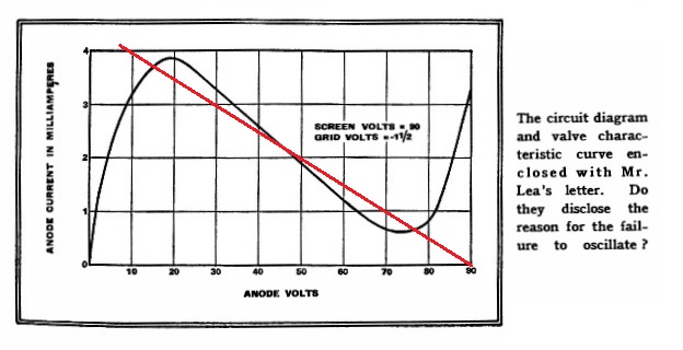
there has been a little delay in posting this, and that has given me the chance for a little more doodling. It has been interesting to check on the characteristic curves of a valve, the 6V6 beam power tetrode which I know was used as a Class C amplifier by amateurs in the old days. A 6V6 would give 4 watts in a Class A audio amplifier. I believe that they used to get 15 watts out of one in Class C. Here is a data sheet set of plate characteristic curves. I have added in red a line of best fit (good fit) to the part of the curve that represents the valve being “hard on”.
6V6 Hard On
It looks as if I was justified in choosing a switch with a resistor in series for my simple model above. I will return to this, and then I will try to stick to this century’s technology.

33 Negative Resistance Part 3

33 Negative Resistance Part 3 in which I realize that we need to distinguish between the negative resistance of a component and the resistance of a circuit. Maybe the solution to the tetrode oscillator problem was easier then it first looked. I also expose (but do not solve) a mistake I have made.

Last time I showed that the tetrode negative resistance oscillator, that would not work from a 90 volt supply with a dropping resistor, would work ok with a low impedance 45 volt supply. See earlier posts.

Later I realized that it had not been quite correct to say that the oscillator would not work with a 90 volt supply and a dropping resistor. In fact the originator of the circuit had been quite wrong when he complained that it would not work. It would work all right, it just would not start! This can be shown by starting it with a low impedance supply and letting it continue to run with the dropping resistor.

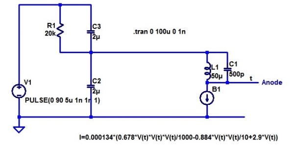
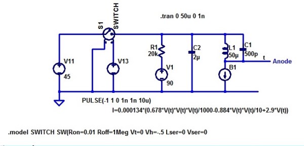
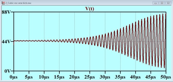
Cubic_osc_arse_kick_circuitThis is what I call my “Kick in the Arse” circuit. It starts off with the switch closed. This provides a low impedance 45 volt supply to establish 45 volts on the 2u cap C2. The oscillator starts. Then the switch opens, and the oscillator continues to operate perfectly well with what amounts to the original circuit!
Cubic_osc_arse_kick_plot

In fact it would have been much more easy than this to provide the required “starting kick”. Consider this circuit:
Cubic_osc_split_cap_circ
Of course, there would have had to be a power switch, or probably two power switches, as it would have been necessary to heat the cathode before applying the starting kick. Again, (in simulation) the oscillator starts and runs.

We might wonder if the simulation model is too “ideal”. A real 90 volt battery would have some series resistance. It might also have properties that dictate that it is not good practice to create large transient currents by placing a microfarad directly across it. I have tried placing a resistor in series with the supply. This resistance can be as high as 1k and the oscillator will still start. You can regard this 1k as modelling the battery intrinsic series resistance, or as an imposed surge current limiting resistor, or you can share the 1k amongst these concepts. It all depends on your line of thinking.

To further drive home the distinction between the negative resistance of a component and of the circuit as a whole, I set out to check the power supply input characteristics of this circuit. First, I tested my oscillator circuit model, and determined that it would start and run with a supply voltage range that exceeds 25 to 50 volts.

Then I set up a model to see how the supply current varied with supply voltage over this range.
Cubic_osc_circuit_current_circuit

The current source and the capacitor C2 provide a voltage ramp. The voltage controlled voltage source E1 follows that voltage and provides current that will not interfere with the current in C2. The resistor R1 has been included to allow C2 to present the lowest impedance shunt path for the oscillator signal. This enabled us to plot the output current of E1 with minimal high frequency ripple.

Let us limbo dance under the barrier to high frequencies presented by the capacitor.
Cubic_osc_circuit_current_plot2

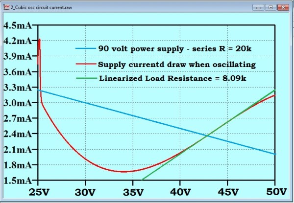
I have relabelled the x axis to show the variable supply voltage, instead of the time, which was the true independent variable in the simulation. The red line is the curve generated by the simulation. The “spike” at the left side, is, I believe an artefact of my start-up transient. Indeed, although I cannot slow down the whole sweep very much, as the simulator is generating data for every cycle of the oscillator, and attempts to run the sweep very slowly lead to the generation of files that are too large for LTspice to handle, I can do a slowed down simulation of just the first couple of milliseconds of the sweep. If I reduce the sweep rate, the height of that initial current spike is also reduced.

The green line is a tangent that I have added by hand to determine the dynamic resistance of the oscillator as a load on the supply. The blue line is the load line for a 90 volt, 20k supply. It is evident that the operating point is completely stable. Note that the operating point is not at exactly 45 volts, but about 43 volts. That is not skin off anybody’s nose.

The ‘split capacitor circuit that I showed above, (repeated here to save you looking back)
Cubic_osc_split_cap_circ

exhibited a characteristic for the first 100 μs like this:
Cubic_osc_split_cap_plot1

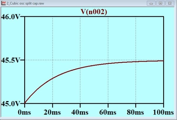
The brown trace is the tetrode anode, and the blue trace is the junction of the two 2u capacitors. It occurred to me that if we run that blue plot for a longer time, we should see it sink to about 43 volts, the stable “operating point” that we determined with the load line above. I did the simulation, and this is what I got:
Split capacitor quiescent point

You can see that the quiescent point for the junction of the two 2u capacitors is about 45.5 volts. I cannot see how this can be different from the operating point we found with the load line (above). Can you?

32 Negative Resistance Part 2

Dear reader,
If you were interested in my first posting on negative Resistance, then I must apologize for such a long delay before I return to the subject. Pressure of other things.

In the first posting, I resorted to an old trick of offering a packet of Smarties as a prize for the best answer to a question that had been put to the readers of Wireless World in April in 1939. I suppose that date puts things in perspective and makes my delay of a few weeks in returning to this look pretty minor.

http://www.keith-snook.info/wireless-world-magazine/Wireless-World-1939/Phase-Splitting%20in%20Push-Pull%20Amplifiers.pdf

You might be wondering where this Smarties business comes from, and what place it has in this serious blog. It all started when I was to address an Historical Society on historical railway matters. I was warned that I might have trouble holding the audience attention. Thus alerted, I planned out several tricks to stimulate audience involvement. Of these, the handing out of little packets of Smarties as prizes for correct answers to questions proved to be the most effective. It is amazing how competitive a room full of senior citizens can be!

So, having brought the joke into this forum, it falls to me to “pay up”. Packets of Smarties have been sent to Brian Magee and James Fenech.

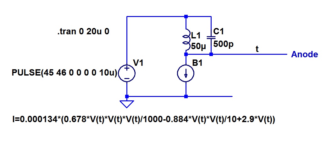
I had gone into this a bit right after the first posting on the matter, and now I come back to my notes, I find that this process seems to be an interesting bit of industrial archaeology in itself. To model what was going on in the Wireless World Circuit (See my earlier posting “http://richardschurmann.com.au/Other/Electronic_Burrow/?p=335”), I chose to use a cubic to provide me with an anode characteristic that had the essential features of the tetrode described. I scratched around with some algebra to work out the equation for a cubic that would seem to pass through the key points. I ended up with:

I = 0.000134 * (0.678E-3 * v^3 – 0.884E-1 * v^2 + 2.9 * v)

The non canonical form of this is a product of the way I derived it. I did not attempt to simplify the presentation of the polynomial, as I could rely on the simulator to multiply out my coefficients at run time.

Here is the tetrode circuit and characteristic as published all those years ago. I have added the load line for the 20k dropper resistor.
Reas circuit 1
Henry_Farrad_3_with_load_line

Here is the result of the simulation:

Not the same, but near enough to explore the key points.

Here is the simulation circuit:
Simulated Rae Circuit

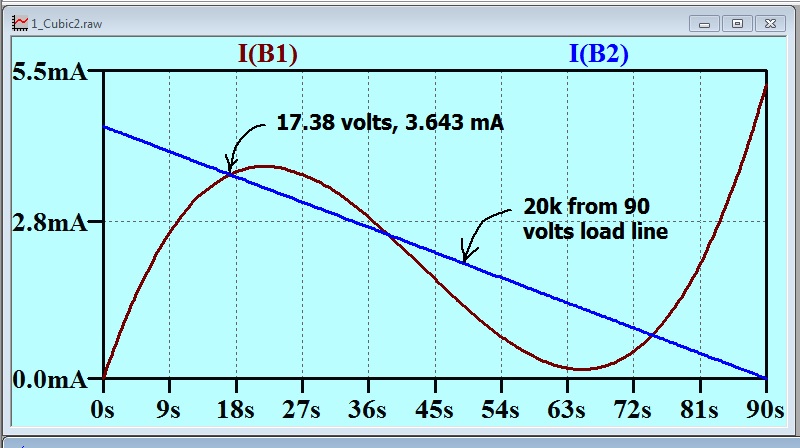
Notice that I have set up my “curve tracer” by offering the cubic response generator with a voltage ramp, which I created by providing a constant current to capacitor C1. This is scaled so that the voltage rises one volt every second. This means that a time domain plot with a time scale marked out in seconds can be read as if the horizontal scale is a voltage scale. The current B1 is the tetrode anode current, and current B2 is for drawing the load line.

The above simulation just showed how my arbitrary function generator loaded with a cubic represented the key features of the tetrode plate characteristic. Then I put that tetrode in the circuit.

You can see that the voltage rises to the first crossing point of the anode characteristic and the load line (round about 17.38 volts).

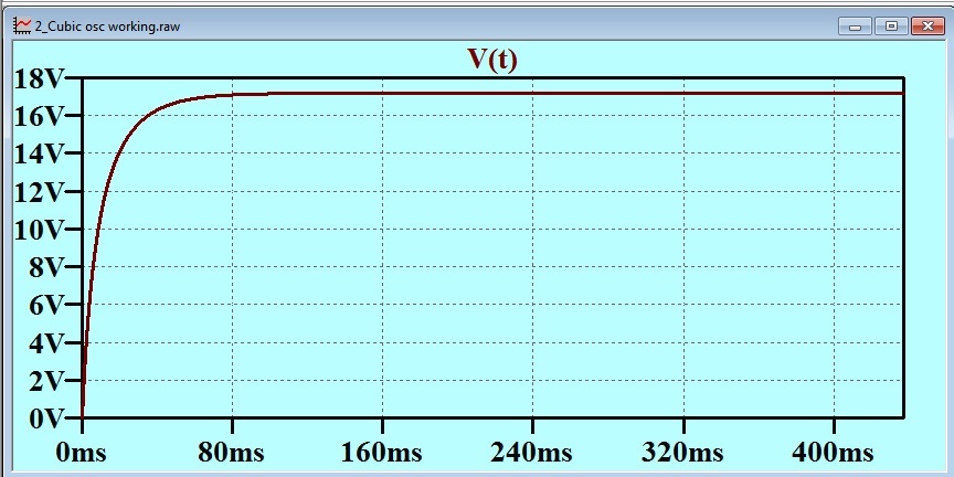
On the other hand, if we power the anode circuit from a low impedance supply at 45 volts, we might get the successful oscillator circuit that was originally wanted.

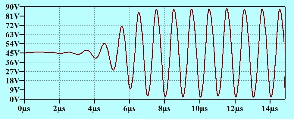
If we run this, we get the Anode Voltage coming out like this:

Which is what was wanted in the first place.

More on this in another post later.

31 Cathode Ray Oscilloscope

In 1965, when I was in Matric (we used to call it 6th form then: both designations that have been replaced) I gave a talk to the physics class on how a radio receiver works. The Physics teacher gave me a very old CRO tube as payment. It has been lovely to have all these years, but I have nowhere to display it, and I have to reduce my stuff.

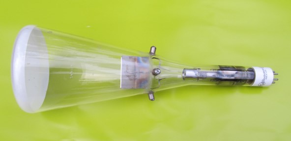
This post is a call to readers for help in finding a good home for it. Quite apart from historical interest, this tube is made in a way that makes all the inner workings clear. Much more so than with what we would have called a “modern one” before oscilloscopes went over to liquid crystal display. It is what we would have called a “five inch” screen, and the tube is about 410 mm long.IMG_0511bis

This is what it looks like. The terminals for the deflection plates are brought straight out through the tube wall and have caps the size of the anode caps on an 807.

IMG_0513

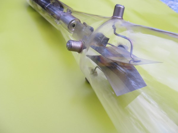
The operation of the deflection plates is easily explained when the form of them is a clear as this!

IMG_0514

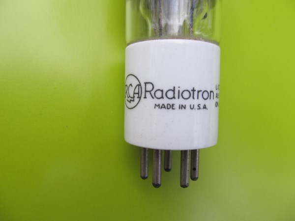
Not as if it is from an obscure manufacturer! The only designation on it is hand written.

IMG_0515

I have conducted various searches for the identity of this tube but to no good effect. When it was presented to me, the tube had been wired up by another student in a circuit spread out on a sheet of plywood. It did work then.

Anyone got a good idea of where I could find a good home for this?

Richard.

30 Negative Resistance

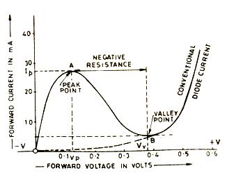
I remember that when I was a youngster, my grandmother commented that “they” were saying that transistors would take over from valves. I reported that I had read in the magazine “Radio and Hobbies” that the transistor was predicted to be taken over by a new device called the “Tunnel Diode”. The tunnel diode dates from 1958, and was in production in 1960. It earned its stripes as an active device, even though it had only two leads, by having a “negative resistance” region in its voltage/current characteristic.

Tunnel Diode

Exploiting or avoiding negative resistance regions had become well established in valve (vacuum tube) days. I had read many explanations of the history of growth of the number of grids in the thermionic valve. The explanations (or was it my youthful, impatient eye) seemed to gloss over the number two. We went from triodes to pentodes, with a very scanty look at tetrodes. There was mention of secondary emission and negative resistance with tetrodes, but these notions were quickly glossed over.

The Radiotron Designer’s Handbook (mine is 4th edition; 1955 but this matter might not have been revised since the first edition in 1934.) mentions secondary emission from the anode in a tetrode (pp7) but in that section does not mention that this can give rise to negative impedance at the anode. In the chapter on oscillators, there is mention of a “Negative transconductance oscillator”, but the design described does not utilize the negative impedance of the anode in a tetrode. (The Radiotron Designer’s Handbook might not be considered children’s reading, but nevertheless, I wish the Father Christmas had been on to it in the early ’60s.)

I remember one construction article in which tetrode characteristics were wanted, and this was achieved by selecting a pentode in which the suppressor grid was connected to a separate pin, rather than connected internally to the cathode. Youngsters who are not familiar with this talk and are interested might like to check the Wikipedia article (http://en.wikipedia.org/wiki/Vacuum_tube) on this which is mostly good stuff, and very little piffle.

I remember a discussion amongst juvenile philosophers at a railway volunteer work party in which we discussed negative resistance, but dismissed it as impossible as it implied that the device was a source of energy. We had not learned to distinguish between E/I and dv/di.

Negative resistance characteristic of tetrodes was exploited in trigger circuits, which could be configured to “snap” between stable states if set up so that the negative resistance region imposed an “S” bend over the load line.

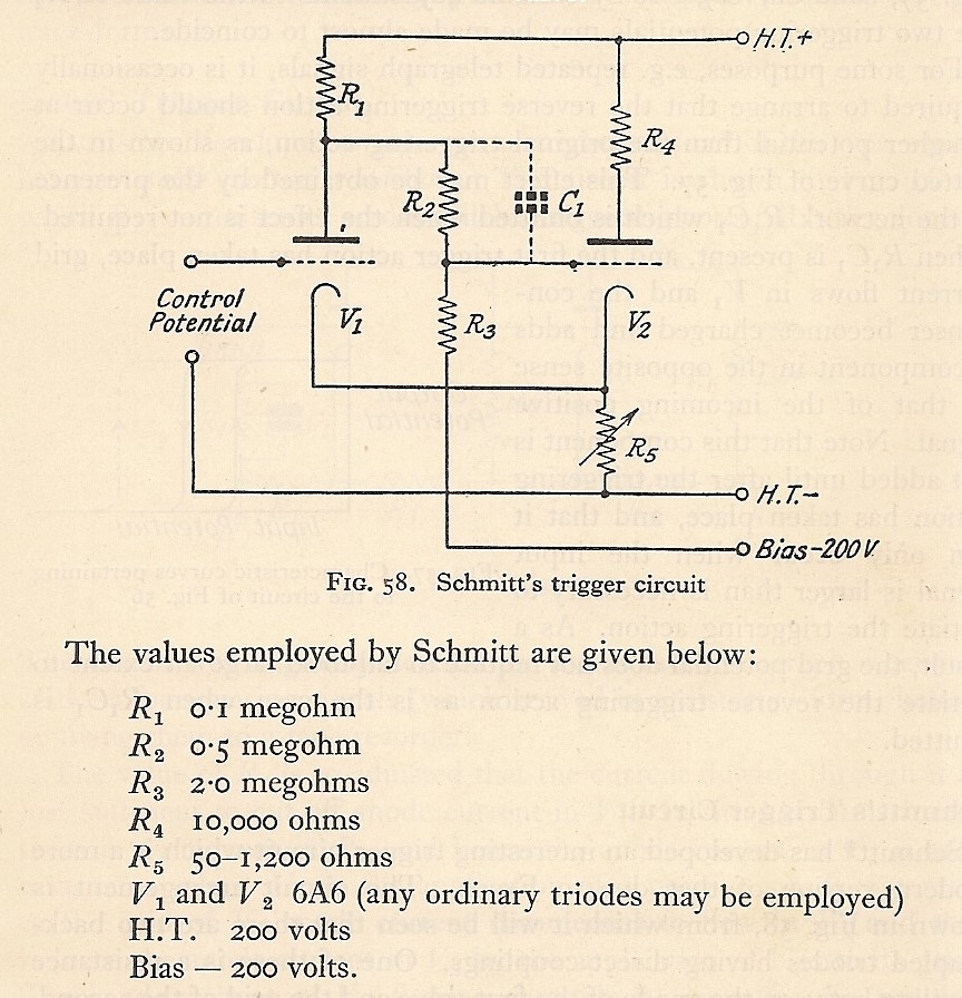
In his book “Time Bases” (1943) Puckle gives several examples of peculiar bias arrangements of tetrodes to obtain a characteristic curve with a negative resistance region in it. The earliest citation for a work describing ways of obtaining negative resistance was from 1935. The motivation in those days was the ability to build a trigger circuit with only one valve. There were many two valve trigger circuits in those days: one of course being the well known one by Schmitt which used two triodes. Schmitt’s trigger had particular features that distinguished it from the several alternatives available to the designer in those days. These features are mostly absent from the arrangements of positive feedback around a comparator or op-amp that is commonly called a Schmitt Trigger today.

The motivation to “use only one valve” must have been very strong in the days when a valve cost about £1/-/- and the average weekly wage was about £20/-/-. This would put its cost in today’s (2014, Australia) money at about $29.00.

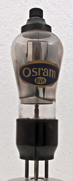
One circuit used the MS4 tetrode.

MS4 Valve

This MS4 Valve picture is from the National Valve Museum http://www.r-type.org/exhib/aaa1359.htm. This motivation to use tetrodes in this way was overcome by the introduction of integrated circuits, although we didn’t use that term then. The trick was to put two triodes in one bottle. A Schmitt Trigger could then be built using “one valve”.

Schmitts Trigger

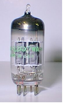
Two triodes in one bottle. Enabled a Schmitt’s trigger to be built with “one valve” and killed the tetrode “negative resistance” trigger.

12AX7

As an aside, in modern circuitry, we could be justified in calling this:

Transistor Schmitt trigger

a Schmitt Trigger, but not really this:

Not Schmitts Trigger

In spite of the fact that this circuit comes from the Wikipedia page for “Schmitt Trigger”, it owes nothing to Scmitt’s circuit. It is a lost cause, but it would have been better if such a circuit were called an “hysteretic trigger’ or just a “trigger”. (Sigh!)

Note that the transistor circuit (above) seems to have been derived from Schmitt’s two triode circuit without much thought. It will generally be found that the VCE(SAT) of the first transistor is less than the VBE of the second. R1 and R2 are thus both unnecessary. Replace R1 with a short, and R2 with an open circuit.

This negative resistance business is important in modern electronics engineering. I gave an example in my post number 14 “Is a skim across the top worse than no analysis at all?” and number 15 “Load Line” (both October 2013). Another example arises in the use of a resistor for “soft start” of a switched mode supply. I might treat this in another post. I will finish this post with a last blast from the past.

For a recent post, I was looking up M. G. Scroggie (“Cathode Ray”)

http://en.wikipedia.org/wiki/M._G._Scroggie

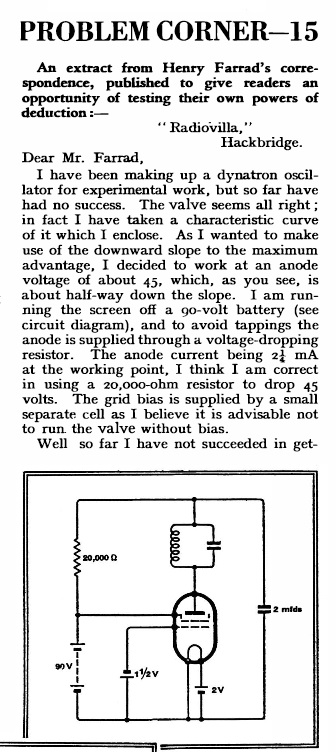
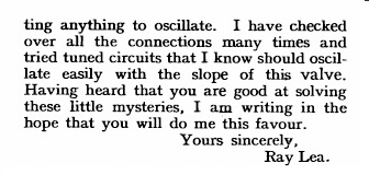
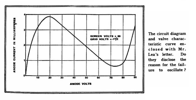
and I came across this delightful conundrum.

Henry Farrad 1Henry Farrad 2Henry Farrad 3

I will leave this hanging in the air just for now. I will give my explanation for Mr Lea’s problem next post. In the meantime, I offer a packet of Smarties for the best reader’s solution.

29 I did the Test Question – and Failed!

I mentioned in my last post that M.G. Scroggie, writing under the pseudonym “Cathode Ray” wrote reminiscences of years of interviewing in an article in “Wireless World”. Many “Cathode Ray” articles can be found at the site http://www.keith-snook.info/wireless-world-magazine/wireless-world-articles.html, but not, as far as I can tell, this particular one.

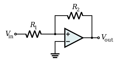
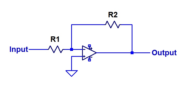
Like me, Scroggie found that the simplest questions can be useful for distinguishing between candidates on the most subtle points. He had a favourite question. He would present the candidate with this circuit:

Scroggie Circuit

His question was “What is the Voltage Gain of this circuit?”

Nearly all candidates would have a crack at it and write:

                             R2

Voltage Gain = ———–

                             R1

Scroggie would reply: “No. That is not what I want.”

The candidate would then try complicating the matter in all sorts of ways. They would offer a more complicated expression that took into account the finite gain of the op-amp. They would introduce the op-amp dominant pole frequency and derive an equation that was an expression of frequency.

To all these efforts, Scroggie would say “No”.

In the end he had to tell them what he was after: a minus sign!

If the circuit is inverting, then the voltage gain is a negative number. Scroggie was a stickler for details such as this, and I learned several rules from him for conventions that can help me from making errors by such means as getting the sign of an expression wrong.

That Scroggie article appeared many years ago, but I have never forgotten the lesson. Thus when James posed his question, which I repeat here:

“Design a one transistor amplifier with a gain of three.

 – 9V supply rail.
– 5k drive impedance to drive YOUR amplifier.

 – 22k load impedance driven from YOUR amplifier.

 – 20-20kHz operation.

 – gain of 3.

 – AC coupling required.

 – Output voltage of 1Vp-p.

 – 1 transistor only.”

“This is reasonably easy,” he wrote, “but requires getting a lot of things in line.”

I was alerted to possible complications when I read the “requires a lot of things in line” bit.

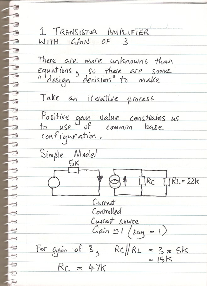
I interpreted this as a potentially tricky question because the required gain is a positive number. This indicates that the amplifier is to be non-inverting. The alternative interpretation, that James (like Scroggie’s candidates) had simply ignored the sign, seemed less likely in the face of those warning words. So I had a crack at it. Here is my effort.

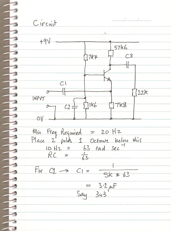
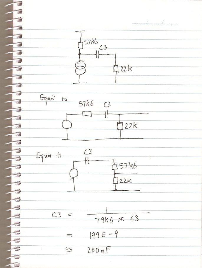
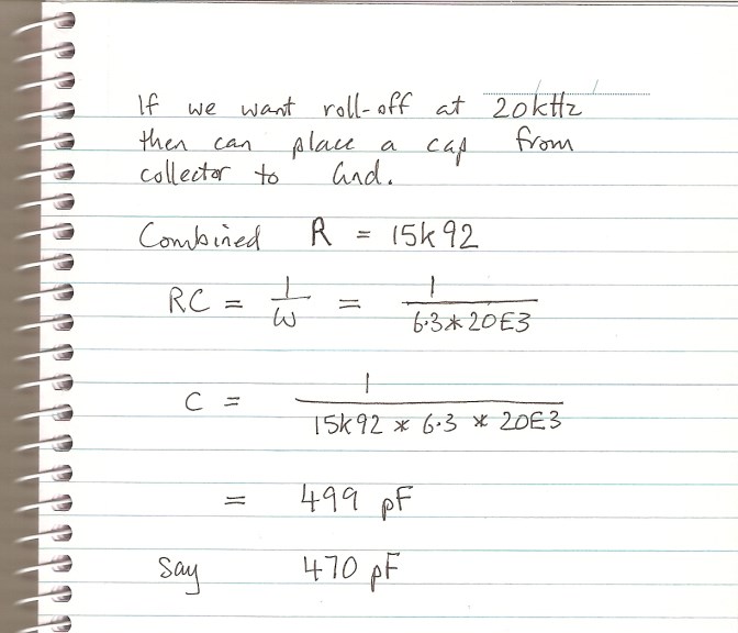
Gain  of 3 page 1

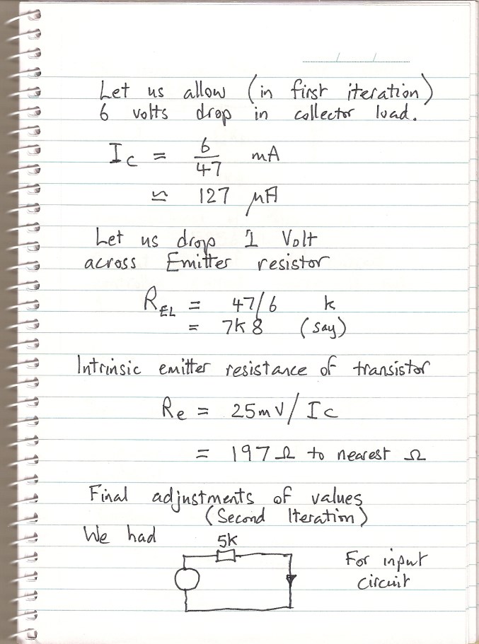
Gain of 3 page 2

Gain of 3 page 3

Gain of 3 page 4

gain of 3 page 5

Gain of 3 page 6

Gain of 3 page 7

Now, first of all, I will mark my own work. What you see above is what I was able to do in examination conditions, although I have written it out again more neatly for you.

In the hand written text above, I have used the term “Transresistance” which is WRONG! What I meant was “Reciprocal of Transconductance” which is not the same thing!

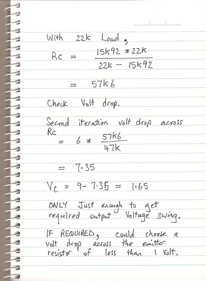
I realized later that I could reduce the collector current, and consequently the volt drop in the collector load resistor just by increasing the value of the emitter load resistor. Indeed, after I had put it up on the simulator, I did increase the emitter load to 9k1, and the small signal response did not change at all. There would have been a little more headroom without transistor saturation, and although I have not even estimated the effect of temperature, the more room to move the circuit has, the more it will be tolerant of changed bias conditions as the VBE changes.

So I sort of had a circuit together in my quick single session with a note pad and a calculator. I was certainly able to make some minor improvements over the next couple of hours, but those hours would not have been available in a job interview test!

How did I do?

My Circuit

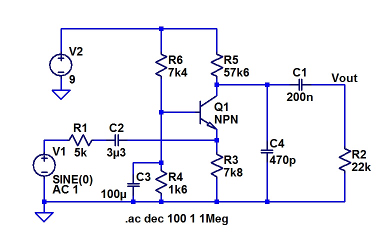
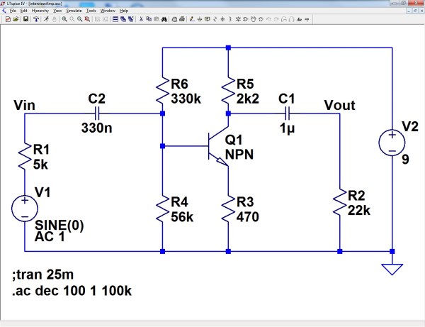
Here is the circuit in LTspice before I changed the emitter load resistor.

.

.

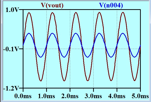
My circuit No Inversion

It has a gain of 3 with no inversion.

.

.

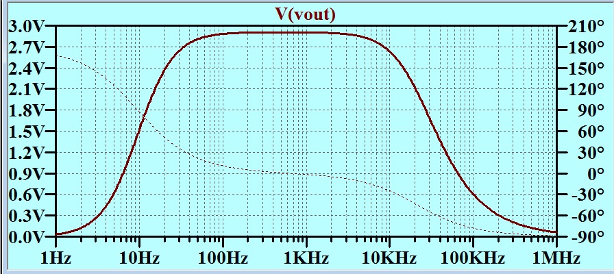
Mycircuit Linear gain

This is not a Bode plot. The vertical axis is linear. ALMOST made a gain of 3! Could quickly tweak this in a real world situation, of course.

.

.

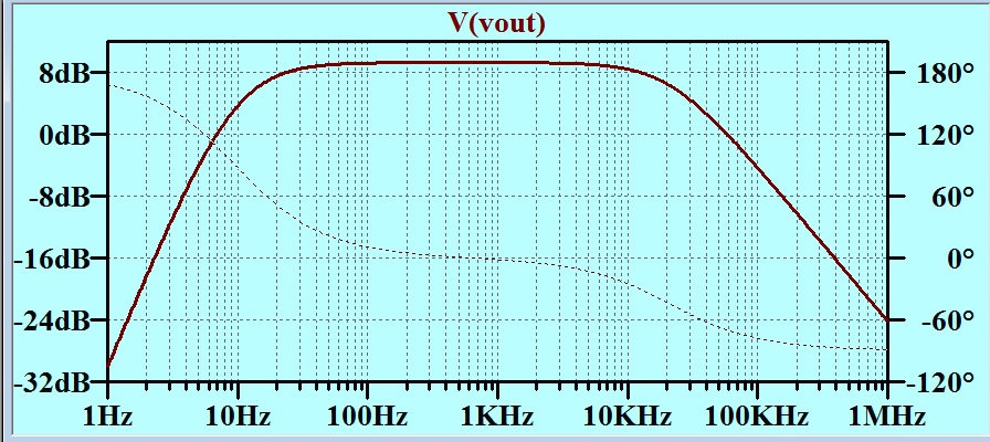
My Circuit Bode

Here is a Bode plot showing how well I did at setting the bandwidth limits.

All this is all very well, but it turns out that I took myself (and you) up a wattle, as this was NOT what the examiner wanted. James was not being pedantic about the minus sign!  He wrote to me later to show what he wanted. Here it is:

James (600 x 461)

Oh Well! I guess I failed that test!


28 Interviewing for a Job

Before I get down to the subject in hand, I need to draw your attention to a much improved power cable based hi-fi equipment enhancer. If the placebo effect (see comment from Nigel Machin to last post) works as he says, then this must be much more effective than the item I wrote about last time. Is there any limit to this?
http://www.tweekgeek.com/bybee-holographic-ac-adapter/

And now, for something completely different.

I recently had a little innocent fun reading blogs that I had been referred to by an employment agency. There was lots of interesting advice for the job applicant. There was not much advice offered for the applicant interviewer/selector. They are both difficult – being an applicant and being a person who must choose between the applicants.

I have done a bit of both over the years, and if I had not been taking the outcome so seriously, I would have found the process of observing the person across the desk from me very interesting. The interest arises from reflecting on the experience later.

There are many aspects of this that do not relate to the technical aspects of the job of being an electronics engineer. The psychology of both roles is interesting. The way both parties give so much more away then they realise is something that can only really be grasped much later, often when the experience of many of these encounters can be brought to bear. I reserve discussion of the non-engineering aspects for another forum, but there are some interesting points relating directly to the question of just what grasp of electronics the candidate has.

I have been the interviewer/selector more times than I have been the candidate, and will share some lines of questioning that I liked to use.

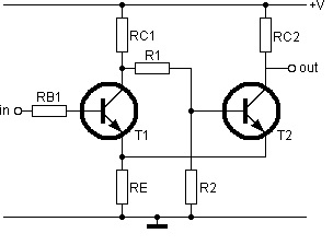
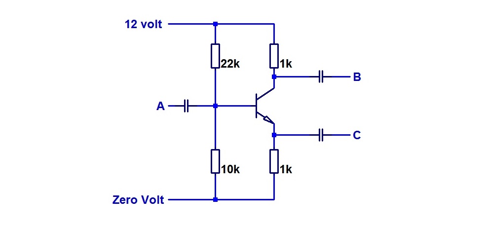
Here are two circuits that I have used many times over the years when interviewing candidates for junior engineer or technician positions. One of the reasons that I stuck with these circuits was that I discovered that after I had used them a number of times, I picked up patterns of response. Once I had calibrated these circuits, the candidates betrayed an awful lot about themselves very quickly. I had been reluctant to publish these in the past, because I did not want to encounter candidates who had swatted up on them. I think that that is unlikely now. Possibly these circuits are a little dated. Perhaps anyone wanting to use circuits such as these as test questions might want to change them a little to suit modern conditions. There is one analogue and one digital.

Analogue Circuit.

Analogue Circuit

I didn’t come to the interview with this circuit printed out: I would sketch it in front of the candidate. Thus the candidate would have the time it takes to draw this freehand to take it in.

My first question would be “What is this?”

This is not the sort of question that has only one answer, but it is a question that gives the candidate plenty of scope to show how she understands what is shown.

I showed this to Ed Cherry when he was still at Monash. He told me that the Monash students did not study the “Concertina” circuit, as if that somehow made it a bit unfair to ask them about it. I reckon that what makes this circuit a really good interview question is that it gives the candidate who has never seen such a thing before a chance to show how she figures it out.

(Concertina circuit: http://www.r-type.org/articles/art-010p.htm. The circuit was also called the “cathodyne” in valve days http://www.valvewizard.co.uk/cathodyne.html.)

My next question would be, “What dc voltages would you expect to see on each of the terminals of the transistor?”

This immediately separated the sheep from the goats. I have had all sorts of weird responses to this question. I have even had a candidate attempting to work this out starting from the collector. I would often be asked about how accurate an answer I needed. I would say “Imagine that this had just been prototyped, and I asked you to check that the dc conditions seemed to be ok. You make measurements, but what do you expect? How do you judge if the measurements indicate a problem or not?

The next matter was small signal performance. I drew a small sine wave on voltage/time axes at the input, and two vacant sets of axes beside the outputs, and asked the candidate to show me what signals, to the same scale, I would expect to see on the outputs.

Analogue Circuit2

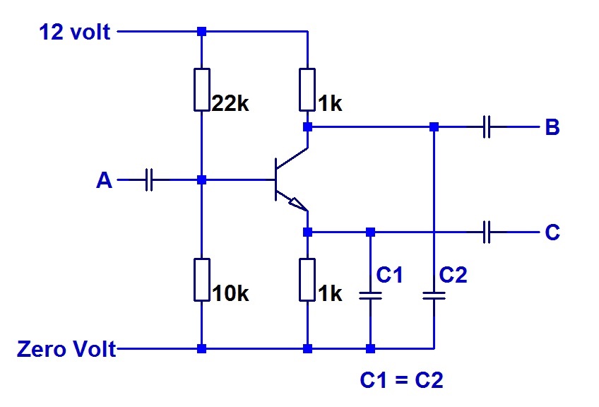
This is such a simple circuit, and yet at this point it had shown huge discriminating power amongst the hundred or so candidates that I have put it to over the years. For the candidate who seemed to be finding it easy sailing, I would propose some capacitative load on each output and ask for some indication on an asymptotic (straight line) bode plot of what effect this would have.

C_Load

I’ll give you a hint that I did not give them. I would like to have seen bode plots representing emitter voltage, collector current and collector voltage in that order.

A Digital Circuit.

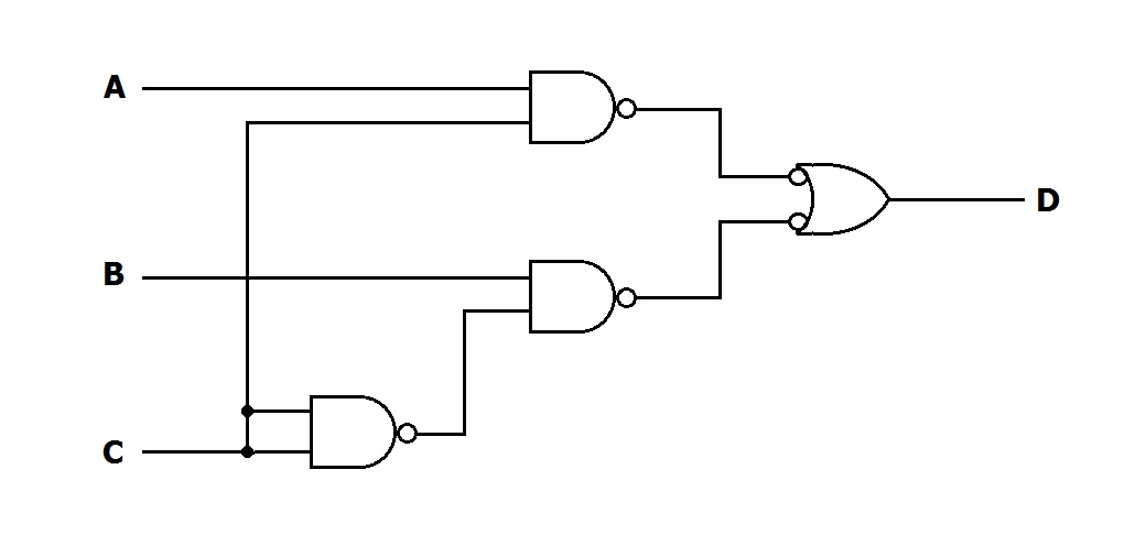
Then I would draw a digital circuit. This is what I would draw.

Logic_Circuit

Some people were not familiar with the appearance of a logic symbol with an inversion bubble on the inputs. I always felt that this was a strange sort of naivety. Nevertheless, for those who had never seen such a symbol, here was a chance to think on their feet and show how they could figure it out. This circuit was drawn using a convention that used to be common of linking outputs with inversion bubbles with inputs with inversion bubbles whenever this is possible. This circuit also shows that this is not always possible.

My first question would be, “What is this?”

This time the initial question is one with a single correct one-word answer. To get this right straight away, rated the candidate highly. For everyone else, I would ask, “How would you describe the signal D in terms of the signals A, B, and C?”

Perhaps in the case where the candidate was struggling, I would ask “Can you tell me what

DeMorgan’s Theorem states?”

( http://www.allaboutcircuits.com/vol_4/chpt_7/8.html )

It always impressed me how much I could learn about a candidate with these two very simple circuits.

I was discussing these with my friend James Fenech, and he mentioned the alternative idea of giving the candidate a prepared test. That can be a good idea too. I have only sat a set test for a job application once. It was a cleverly contrived test with some tricky traps. I fell into a couple of them. James suggested that one could start with line of thinking such as my really simple analogue circuit (above) and set a task such as “Design a one transistor amplifier with a gain of three”. This reminded me of an article that was written in Wireless World by M.G. Scroggie who used to use the nom de plume “Cathode Ray”. He discussed a lifetime of interviewing young engineers and observed how the candidates had changed over the years. He had a pet question about the gain of an op amp. I don’t think that it was supposed to be a trick question, but it turned out to be a bit tricky for the modern candidate.

Was James’ question a “trick” question? To try to clarify this, I asked him for a more detailed specification. He replied:

“If I were setting such a question:

 – 9V supply rail.

 – 5k drive impedance to drive YOUR amplifier.

 – 22k load impedance driven from YOUR amplifier.

 – 20-20kHz operation.

 – gain of 3.

 – AC coupling required.

 – Output voltage of 1Vp-p.

 – 1 transistor only.”

“This is reasonably easy,” he wrote, “but requires getting a lot of things in line.”

I still couldn’t decide whether this is a trick question or not. I had a crack at it. With one interpretation of the requirement, I found that it was only just possible. maybe this is what James meant when he wrote “… requires getting a lot of things in line.”

Hmmmmmm.